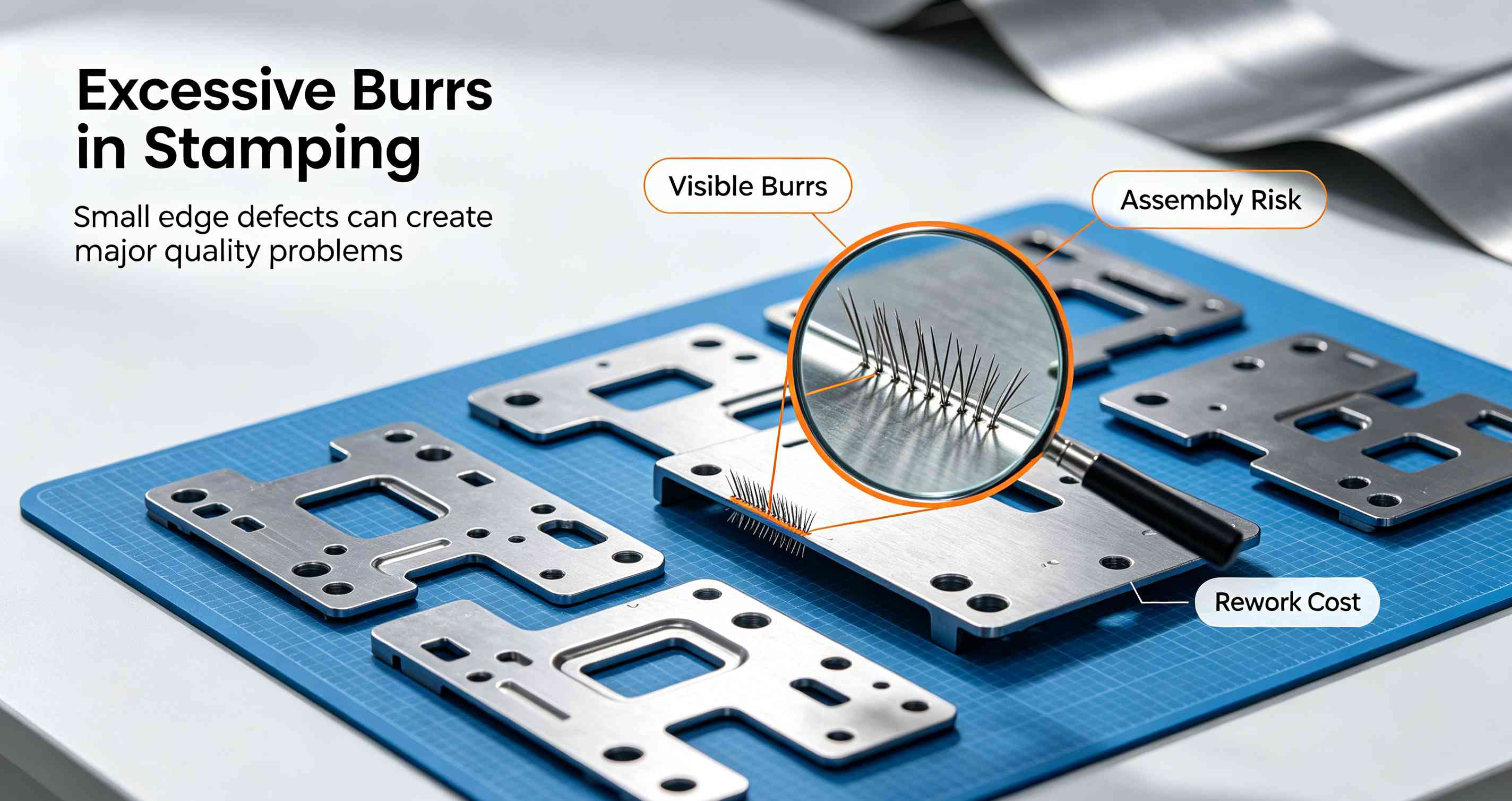
Friends working in hardware stamping are most likely to have been severely troubled by the burr issue.
The product was flawless during the trial molding, but after mass production, burrs suddenly exceeded the standard; Using the same mold, switching batches of raw materials leads to mass production defects; Minor burrs may affect the appearance and quality, while severe cases can cause assembly jams, scratch workpieces and operators, or even compromise product sealing and electrical performance. This directly leads to customer returns, deductions, and delivery delays.
Many factories address burrs by blindly polishing, grinding, and adjusting molds, which only treats the symptoms without addressing the root cause. Repeated rework not only consumes manpower and slows down production capacity but also significantly shortens the service life of the molds.
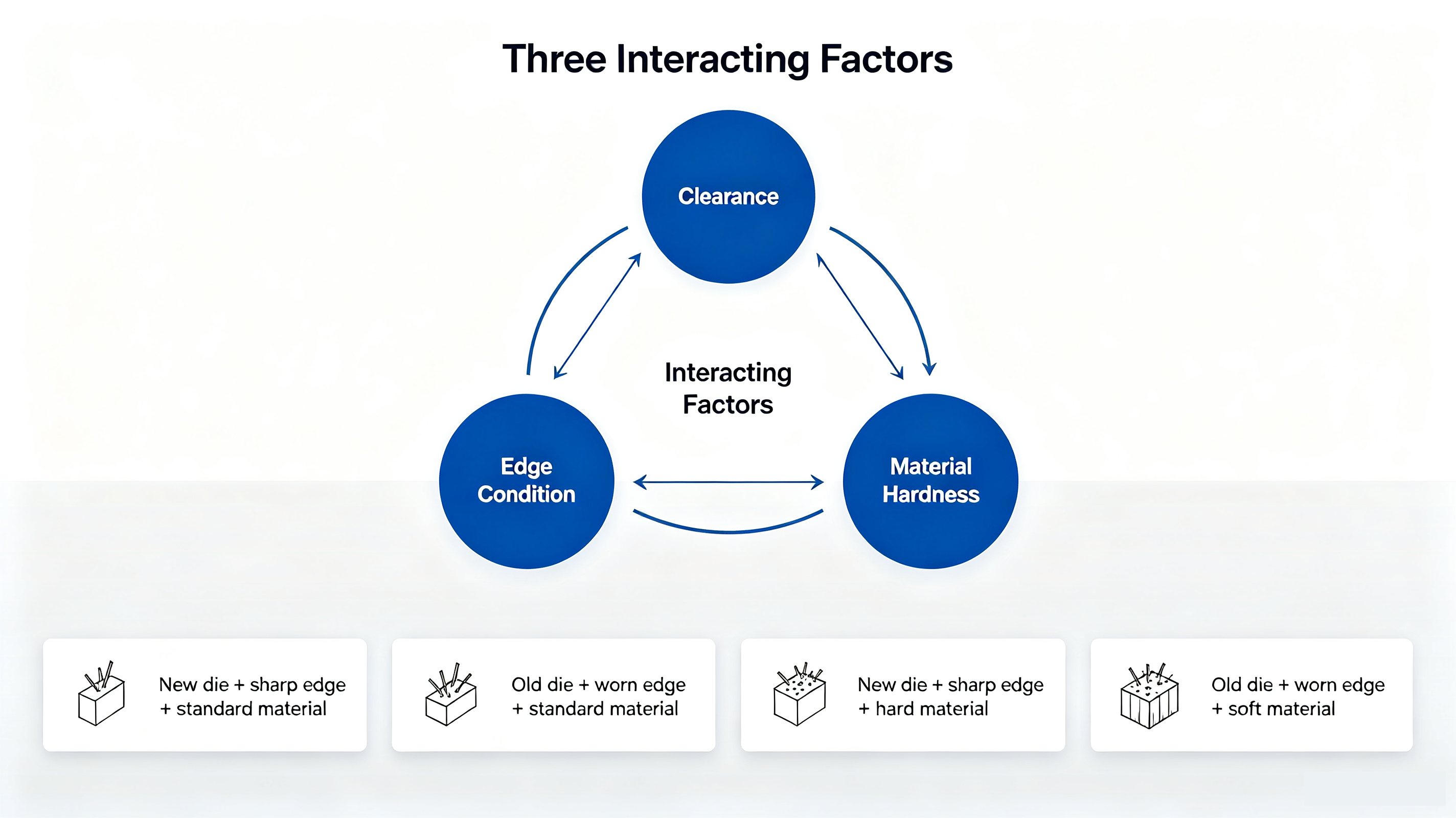
In fact, burrs on stamped parts are never "accidental defects"; they are an inevitable result of the combined effects of three core factors: gaps, blade edges, and material hardness. Today, from a hands-on perspective, we will thoroughly explain the underlying logic of burr formation, along with practical debugging and control solutions that can be immediately implemented. This will help everyone address 90% of stamping burr issues at their root cause.
Shearing Clearance: The Core Factor Determining Burr Size
The shearing clearance refers to the unilateral distance between the punch and the die. It is the most critical fundamental parameter of a stamping mold, directly determining the quality of the stamped cross-section and the form of burrs. It also serves as the primary control point for adjusting and eliminating burrs.
The standard punching cross-section is divided into four main areas: the folded corner zone, the bright band, the fracture zone, and the burr zone. The proportions of these four areas are entirely determined by the size of the punching clearance. If the clearance is incorrect, even with brand-new molds and high-quality materials, burrs will inevitably appear.
Excessively small clearance: The burrs are short, hard, and extremely difficult to remove.
When the actual gap is smaller than the material compatibility standard value, the upper and lower tearing cracks of the material cannot be precisely aligned, resulting in a secondary shearing phenomenon that extends outward and produces a double shiny band. The final burrs produced, although not long, have thick bases and hard texture, making them difficult to clean off with ordinary grinding.
At the same time, excessively small gaps will significantly increase friction and wear on the punch and die, causing the mold to wear out quickly, resulting in increasingly poor burr formation with each subsequent punching operation.
Real-world case: A certain automotive connector terminal product with a material thickness of 0.6 mm and an initial single-sided gap of 0.02 mm (gap rate 3.3%). After 5,000 mass production stamping cycles, the burrs exceeded the standard directly, reaching 0.08 mm. After fine-tuning to a unilateral 0.035mm (clearance rate 5.8%), the burrs were reduced to within the acceptable range of 0.025mm, directly extending the mold life by three times.
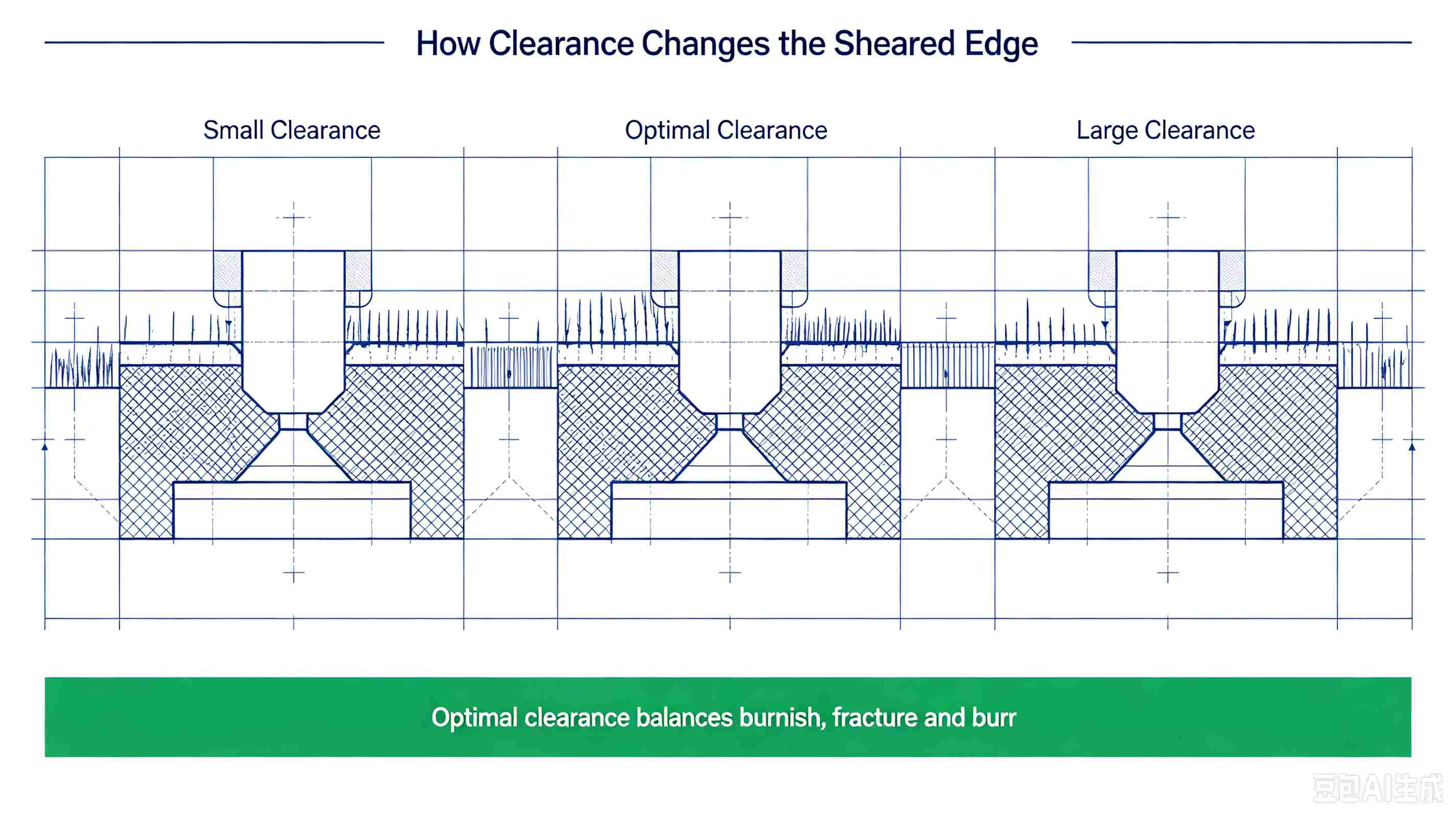
Excessive clearance: Burrs are long and thin, prone to falling off, resulting in complete loss of precision control.
When the gap is excessively large, the material's tearing cracks propagate inward, significantly increasing the rough fracture zone and substantially enlarging the coarse fracture band with a much larger rough fracture zone, while sharply reducing the smooth and shiny band, leading to a drastic decrease in the smooth and lustrous band. The resulting burrs are long, thin, and weak. Although they appear easy to clean, they easily fall off and leave residues, causing product contamination and assembly jams. Additionally, the dimensional accuracy and flatness of the workpiece are significantly reduced, failing to meet the requirements for precision component production.
General Reasonable Clearance Rate for Various Materials (Single Side)
There is no universal fixed value for the gap; it must be matched according to the material properties. Mature industry standards can be directly referenced:
- Soft steel (SPCC, Q235): 5%–8%
- Stainless steel (SUS304): 6%–10%
- Copper and copper alloys: 4%–6%
- Aluminum and aluminum alloys: 5%–7%
- High-strength steel (AHSS): 8%–12%
Note: The above values are basic reference parameters. During mass production, adjustments must be made based on the die specifications, material hardness, and pressing speed to ensure proper adaptation.
Edge Condition: The mold deteriorates with use, and the root cause lies in wear.
Many people are puzzled: The new mold produces no burrs, but after a period of mass production, the number of burrs increases significantly. The parameters haven't been changed, and the equipment hasn't been replaced. Where exactly is the problem? The most likely answer is: wear on the die edge.
During the stamping process, the die edges continuously endure high-intensity impact forces and friction. As the number of stamping cycles accumulates, sharp edges gradually develop issues such as rounding, chipping, coating flaking, and localized defects.
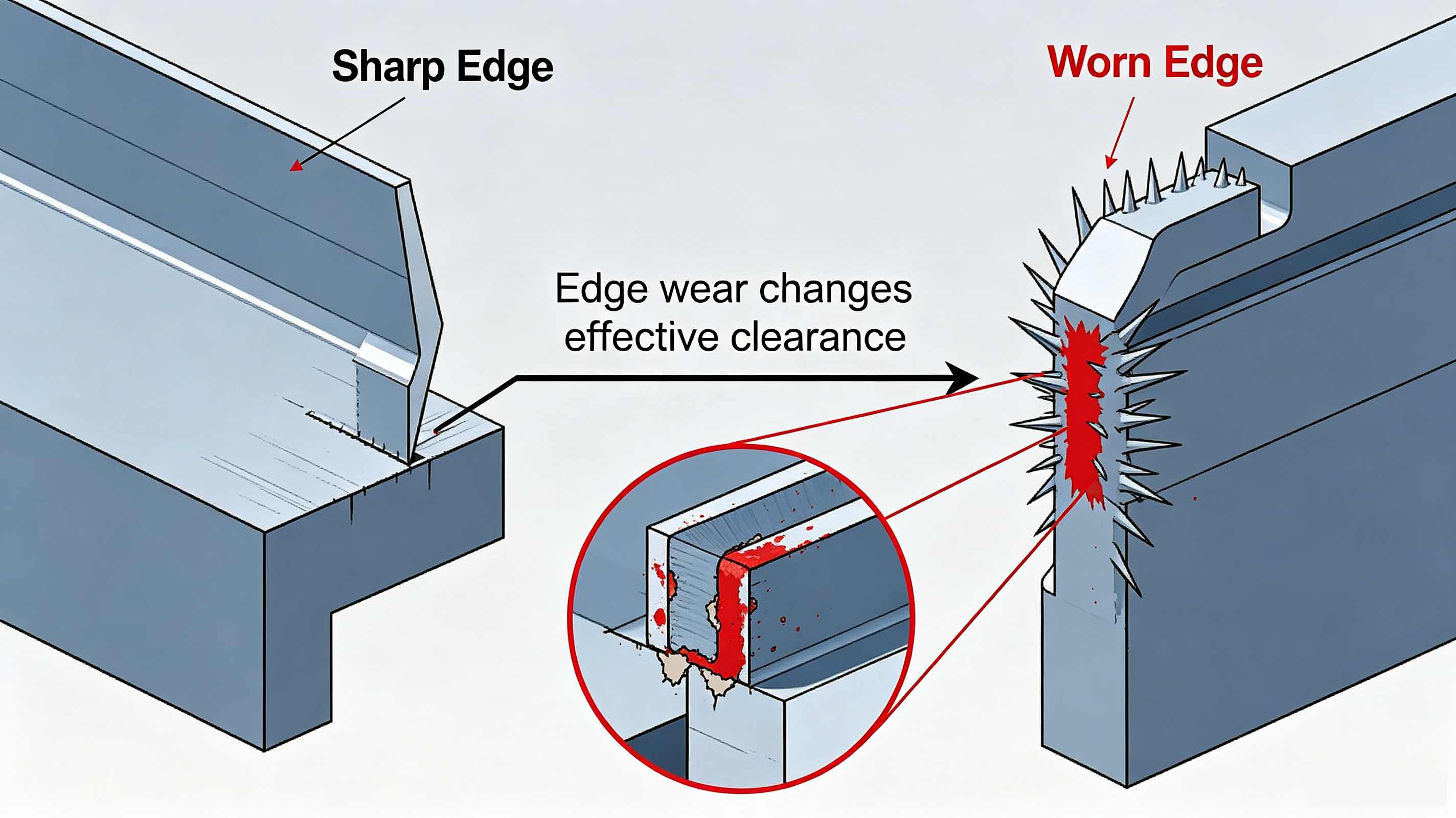
1. How does edge wear lead to the formation of burrs?
Blade wear will indirectly alter the actual punching clearance: as the punch blade edge becomes rounded, the effective clearance decreases; The die edge becomes rounded, and the effective clearance increases; Uneven wear on the upper and lower cutting edges can result in asymmetric gaps.
The final outcome is: the burrs continue to grow larger, the cross-section quality becomes unstable, and the faults exhibit a highly regular pattern.
2. Quick Diagnosis: Is your burr issue related to the cutting edge?
The product exhibits uniform burrs around the entire circumference, which gradually increase with each molding cycle: this is usually due to overall edge wear or baseline gap deviation.
The appearance of burrs on single sides or local segments of the product is entirely due to localized edge chipping, defects, or deviations in mold parallelism.
3. Practical Solutions for Extending Blade Edge Life and Reducing Burrs
Preferred mold materials (wear resistance from low to high): Ordinary Cr12MoV mold steel (sufficient for regular mass production) → ASP23/ASP30 powder metallurgy high-speed steel (preferred choice for large-volume precision stamping) → Cemented carbide (ultra-high wear resistance, but brittle and unsuitable for strong impact conditions).
Key details in processing and maintenance: After wire cutting, retain the high-gloss edge; manual polishing is prohibited (as it damages the microstructure of the edge and accelerates wear); Match coatings according to requirements: TiAlN is suitable for high-speed stamping, DLC for non-ferrous metal anti-sticking molds, and BALIQ for high wear-resistant applications; Regular blade sharpening and maintenance to promptly restore edge sharpness.
Material Hardness: The Most Easily Overlooked Hidden Cause of Burrs
Using the same mold and the same set of parameters, but switching to a different batch of materials, results in defects such as burrs and quality issues—this is a common occurrence in the industry. The core reason is: batch variations in material hardness and plasticity.
The hardness of materials directly determines their resistance to shear and their capacity for plastic deformation. Materials with different hardness levels yield vastly different results in punching and forming processes.
1. Characteristics of burrs in materials with different hardness levels
Soft materials (pure aluminum, brass): Extremely high plasticity, significant deformation before fracture, large collapsed corners, prone to generating substantial burrs, and difficult to clean.
Medium-hardness materials (SPCC, SUS304): Exhibit moderate deformation with uniform cross-sections, making them the easiest to produce high-quality products without burrs.
Hard materials (65Mn spring steel, high-strength steel): High brittleness and rapid fracture speed, with relatively small burrs, but they exert extremely strong impact on molds, often leading to edge chipping.
2. For materials of the same grade, why are there significant batch differences?
Even with uniform material grades, different batches of materials may exhibit variations: hardness fluctuations can reach HRB 5-10, differences in annealing processes lead to variations in plasticity, surface oxides, oil contamination, and uneven plating thickness. These minor discrepancies are amplified during high-speed stamping, resulting in batch-scale burr defects.
3. Implementation Strategies for Addressing Material Volatility
Dynamic gap adjustment: For harder materials, increase the unilateral gap by 0.5% to 1%; The material is too soft; appropriately reduce the clearance.
Strict control of incoming material quality: Lock in hardness standards with suppliers, conduct random inspections for each batch of incoming materials, and immediately return non-conforming items.
Optimize mold structure: Key workstations adopt replaceable inserts, facilitating subsequent parameter adjustments based on material conditions.
The Interconnected Relationship of Three Key Factors: Understanding the Context to Precisely Diagnose Issues
In actual production, clearance, blade edge, and material hardness do not act independently; they influence each other. Corresponding to different production conditions, the manifestation of burrs is clear at a glance:
New mold + sharp edge + standard materials: Reasonable clearance, burrs controlled within 0.03mm, offering the highest quality.
Old mold + worn edges + standard materials: burrs increase continuously with each molding cycle, gradually exceeding the standard to over 0.08mm.
New mold + sharp edge + hard material: Minimal burrs, but the mold edge is highly prone to chipping, leading to a drastic reduction in lifespan.
Old mold + worn edges + softer material: Large, hard burrs that are extremely difficult to grind, leading to a sharp increase in batch defect rate. Mass production defect rate surges.
Full-Process Burrs Control Plan (Directly Implementable)
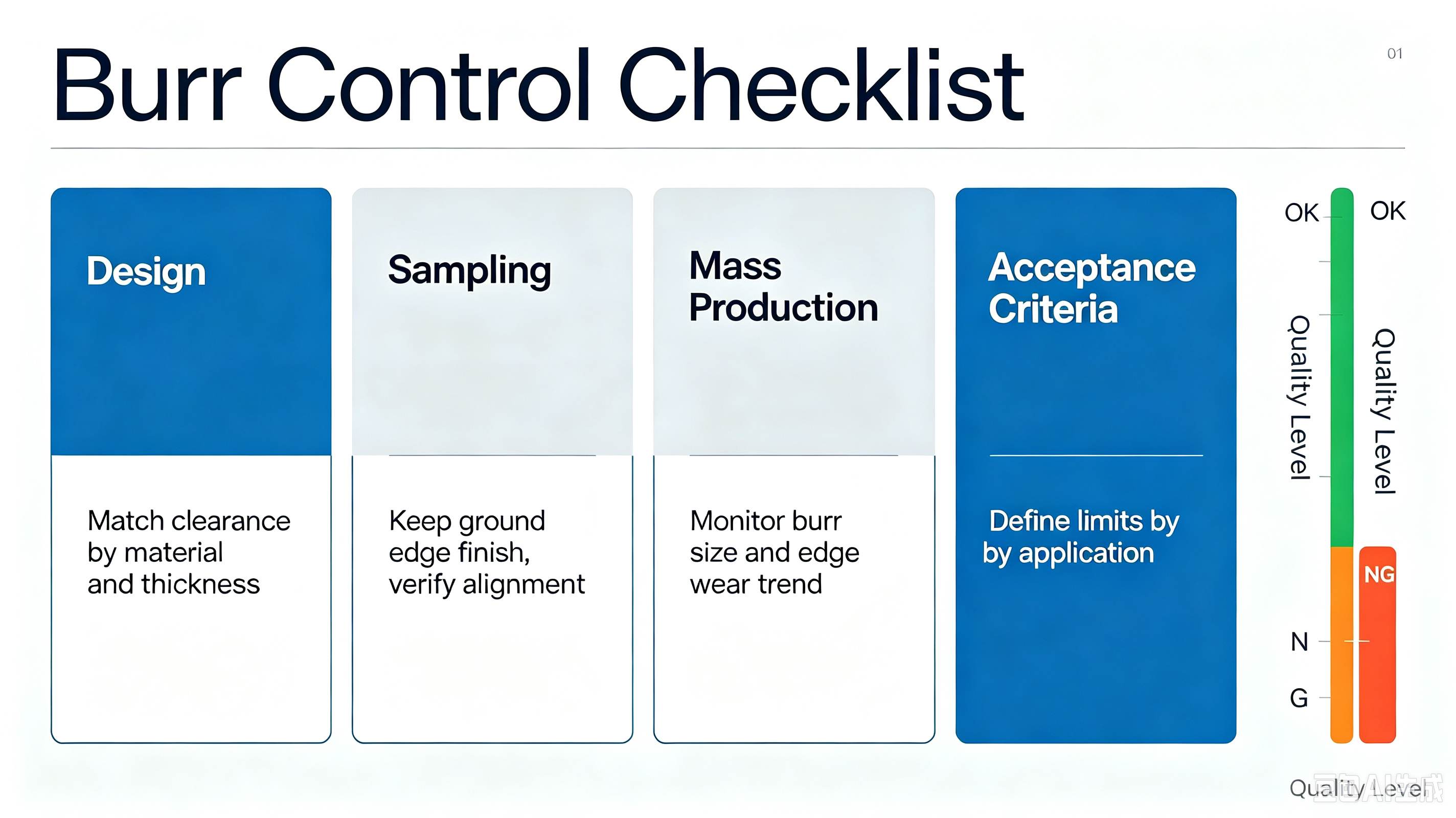
1. Design Phase: Avoiding burr risks from the source
Precisely match the gap rate according to material type and thickness; The key forming and punching positions adopt replaceable inserts, facilitating later maintenance and fine adjustments; Establish clear edge roughness standards, strictly controlling Ra below 0.4.
2. Prototype Mold Manufacturing Phase: Establishing a Solid Quality Foundation
After wire cutting, retain the high-gloss edge to prevent precision degradation from manual polishing; avoid damaging accuracy through hand-polishing. Precise calibration of the punch and die alignment; Conduct a full inspection of the burr dimensions on the first piece; only after it passes will mass production be initiated.
3. Mass Production Phase: Routine Management to Prevent Failures
Establish a burr inspection system for each shift to record data trends; Predict the mold edge grinding cycle based on burr fluctuations; Conduct random hardness inspections on each batch of incoming materials and promptly fine-tune the stamping parameters accordingly.
4. Industry-Standard Acceptable Criteria for Burrs (for reference)
Electronic connector terminals: ≤0.03 mm (to ensure contact reliability)
Automotive structural components: ≤0.05mm (meeting assembly and safety standards)
Home appliance sheet metal parts: ≤0.10 mm (meeting appearance quality requirements)
Architectural hardware: ≤0.15mm (lower functional requirements)
Rushing burrs are never an unsolvable problem; it's just that most people haven't identified the core issue correctly.
When encountering excessive burrs, there is no need for blind grinding, frequent mold adjustments, or repeated trial and error. Remember the precise inspection sequence: first check the material batch and hardness, then examine the wear condition of the die edge, and finally fine-tune the blanking clearance.
By thoroughly understanding the three core factors—gaps, blade edges, and materials—and standardizing the entire process of design, manufacturing, and mass production, we can completely eliminate burr issues, stabilize product yield rates, reduce rework costs, improve delivery quality, and secure customer orders firmly!


© 2026 © HONGYU MOULD LIMITED. All Rights Reserved.
 IPv6 network supported