banner
  • When to Replace or Regrind Stamping Tooling: A Practical Guide for Die Maintenance
    When to Replace or Regrind Stamping Tooling: A Practical Guide for Die Maintenance Jun 17, 2026
    In the world of metal stamping, tooling wear is inevitable. But knowing exactly when to replace a punch or regrind a cutting edge can mean the difference between high-quality output and costly downtime.   When to Replace a Punch Punches are among the most stressed components in a stamping die. Here are the critical signs that it's time for replacement:   Visible Wear or Chipping Inspect the punch tip regularly. If you notice: Rounded or dull cutting edges Small chips or cracks on the surface Uneven wear patterns Replace immediately. Continuing to use a chipped punch can damage the die button and produce burrs on your parts.   Excessive Burr Height Burr height is one of the most reliable indicators. Measure burrs periodically: Acceptable: Less than 10% of material thickness Warning: 10–15% — plan for replacement soon Critical: Over 15% — replace immediately   Dimensional Drift If stamped parts begin to fall outside tolerance, even after adjusting the press parameters, the punch may be worn beyond its useful life.   Increased Punching Force A sudden or gradual increase in press tonnage often indicates that the punch is dull and requires more force to shear through the material.   Surface Finish Degradation When the sheared edge becomes rough, torn, or shows excessive rollover, it's time to evaluate punch condition. General Rule of Thumb For standard tool steels punching mild steel (up to 3mm thick), expect a typical punch life of: 50,000 – 200,000 strokes​ before resharpening Replacement after 3–5 regrinds, or when the punch length is reduced by 20%   When to Regrind Cutting Edges Regrinding restores sharpness without replacing the entire tool. Proper timing maximizes tool life while maintaining quality.   Key Indicators for Regrinding   1. Burr Threshold Exceeded As mentioned above, once burr height reaches 10–15% of material thickness, schedule a regrind. Do not wait until it hits the critical zone.   2. Edge Radius Increase Use an optical comparator or microscope. If the cutting edge radius exceeds 0.05–0.10 mm, regrinding is overdue.   3. Galling or Pick-Up When material starts sticking to the punch or die surface, it indicates micro-welding due to heat and friction. Regrinding removes the damaged surface layer.   4. Sound and Vibration Changes Experienced operators often hear when a die is dull. A change from a clean "snap" to a dull "thud" or increased vibration signals the need for maintenance.   5. Consistent Production Counts Many shops adopt a preventive approach: Regrind every 50,000 – 100,000 strokes​ depending on material type and thickness Track actual performance and adjust intervals accordingly   Recommended Regrind Amount Remove only 0.05 – 0.15 mm​ per regrind Avoid removing too much material at once, as this generates heat and can soften the tool steel Best Practices for Maximizing Tool Life Practice Benefit Use proper lubrication Reduces friction and heat buildup Maintain correct clearance Prevents excessive wear and chipping Align punches precisely Eliminates uneven loading Store tools properly Prevents corrosion and accidental damage Keep detailed maintenance logs Enables data-driven replacement decisions   The decision to replace a punch or regrind a cutting edge should never be based on guesswork. By monitoring burr height, dimensional accuracy, edge condition, and production counts, you can implement a predictive maintenance strategy that reduces unplanned downtime and extends tool life.A well-maintained die is a profitable die.    
  • Impact of Surface Treatments—Nitriding, Titanium Coating, and Sandblasting—on Stamping Die Life
    Impact of Surface Treatments—Nitriding, Titanium Coating, and Sandblasting—on Stamping Die Life Jun 12, 2026
    In daily production of metal stamping dies, issues such as die wear, galling, chipping, and rusting are key factors affecting production efficiency. As the hardness and wear resistance of die base materials are limited, surface treatment processes are the most efficient and commonly used methods to increase the number of stamping operations and extend die life. Among them, nitriding, titanium coating, and sandblasting are the most widely applied techniques. The principles, characteristics, and effects of these three methods on stamping die life differ significantly, and each is suited to specific production scenarios.   Nitriding is the most fundamental and cost-effective long-term surface treatment in the die industry, and is the preferred choice for standard stamping dies. Through high-temperature diffusion, a dense nitrided hardening layer is formed on the die surface. This process does not change the overall dimensions of the die and does not affect assembly accuracy. Nitriding can significantly enhance surface hardness, improving wear resistance, galling resistance, and minor corrosion resistance, effectively preventing sheet galling and moderate wear during stamping. Dies treated with nitriding can achieve two to three times longer service life, making this method suitable for stainless steel, general cold-rolled steel, and other conventional stamping applications. However, its limitations are also apparent: the hardening layer is relatively thin, and impact and high-temperature resistance are moderate, making it unsuitable for high-speed stamping or stamping of high-hardness materials.   Titanium coating is a high-end reinforcement process and is the most effective method for significantly increasing die life. Titanium coating involves depositing an ultra-thin layer of high-hardness, highly lubricious titanium alloy on the die surface. The coating far exceeds the nitrided layer in hardness and offers exceptional wear resistance, high-temperature resistance, and a low coefficient of friction. During stamping, the coating can greatly reduce friction between the die and the sheet, completely eliminating galling, carbon buildup, and sticking issues. Even under high-speed, high-frequency operations, the die surface remains smooth. A high-quality titanium-coated die can last five to ten times longer, making it ideal for high-speed continuous stamping, stainless steel, and high-strength steel in heavy-duty applications. The only downside is the higher cost and the fact that the coating cannot be locally repaired once damaged.   Unlike the previous two reinforcement methods, sandblasting is a physical surface treatment whose main function is not to enhance hardness, but to optimize surface condition. Sandblasting uses high-pressure abrasive particles to impact the die surface, refining the surface texture, removing oxide scale and machining marks, and eliminating stress concentrations. This process improves demolding performance, reduces burrs on stamped products, and slightly mitigates galling issues. However, it does not increase die hardness or wear resistance, offering only a minimal improvement to die life. Sandblasting is mainly used for pre-treatment, improving appearance, and relieving surface stresses.   In summary, each of these three methods has its own advantages and is fit for particular applications. For low-cost, standard mass production applications, nitriding is the preferred choice. For high-speed, high-hardness sheet metal and long-life production, titanium coating is recommended. For pre-treatment and surface finish optimization, sandblasting should be selected. Effectively combining these surface treatment techniques can significantly extend die life, reduce maintenance frequency, lower production costs, and ensure stable stamping operations. Such refined die maintenance and appropriate cost control are the keys to increasing efficiency and reducing expenses in stamping production.
  • Three Core Priorities for Stamping Mold Business Owners in 2026
    Three Core Priorities for Stamping Mold Business Owners in 2026 Jun 06, 2026
    The stamping mold industry has moved past the era of relying on high output and low prices to win orders. In 2026, market homogeneity, rising raw material and labor costs, and increasingly strict customer inspection standards have reshaped the industry competition. It now focuses on stable quality, controllable profits and precise customer resources.   There is no need to chase impractical high-tech concepts or blindly expand production capacity. Focusing on these three practical tasks will help mold manufacturers stabilize their business and stand out from competitors. Prioritize Stable Quality, Abandon Unreliable Mass Production Whether for domestic key clients or foreign trade orders, customers value most is mold stability, fewer after-sales problems and worry-free mass production. Many mold factories have sufficient inquiries, yet lose profits and reputation due to repeated mold modifications, burrs, springback, deformation and inconsistent mold service life during production.   In 2026, quality competition is essentially standardized operation competition. We conduct thorough DFM review, precise layout and structural optimization in advance to avoid cracking, scratching and dimensional errors from the source. During production, we strictly control steel selection, heat treatment accuracy and edge polishing processes. Standardized mold testing is implemented to ensure consistent sample quality.   With solid craftsmanship and standardized workflows instead of fancy intelligent equipment, factories can greatly reduce defective rates, stabilize mold precision and service life — the core to retaining old customers and gaining new referrals.   Adopt Refined Cost Control, Avoid Extensive Profit Loss Industry profits have become highly transparent, and raising prices is no longer a feasible solution. Refined cost control equals profit growth. Many mold factories maintain a steady order volume but gain slim profits, mainly due to extensive cost management.   Successful mold owners focus on detailed cost control in every production link. Adopt standardized and modular mold bases to reduce redundant processing and material waste. Optimize processes upfront to cut repeated mold testing and modification costs. Standardize daily mold maintenance and regular replacement of vulnerable parts to extend mold service life and lower rework expenses.   We match materials and processes reasonably, avoiding excessive cost from over-specified materials and quality loss from cutting corners. Precise cost control is the key to securing profits amid fierce low-price competition. Upgrade Service & Select High-quality Tracks, Stop Blind Low-price Bidding The industry shows obvious polarization in 2026. Low-end orders only bring cutthroat price competition, while emerging tracks including new energy, precision electronics and foreign trade offer stable orders and better profits. Mold owners need to actively target high-value markets such as precision stamping, new energy structural parts and export-standard molds to avoid homogeneous low-end competition.   Meanwhile, enterprises must transform from simple mold suppliers to one-stop solution providers. We offer full-cycle services, including pre-production drawing evaluation and process optimization, mid-production manufacturing and trial testing, and post-production mass production support and after-sales maintenance. For foreign trade orders, we comply with international inspection standards and ensure traceable quality and complete compliance documents to expand overseas markets and get rid of price wars. There are no sudden windfalls in the 2026 stamping mold industry, only steady and down-to-earth development. Stabilize quality to lay a solid foundation, control costs to retain profits, and upgrade services to expand market share. By sticking to these three practical priorities, mold enterprises can survive industry reshuffling and achieve long-term stable growth.  
  • Top 5 Trends Reshaping the Hardware Stamping Die Industry in 2026
    Top 5 Trends Reshaping the Hardware Stamping Die Industry in 2026 May 22, 2026
    The hardware stamping die and mold parts processing industry is undergoing its most significant transformation in decades. As we move deeper into 2026, the convergence of downstream demands—from electric vehicles (EVs) and 5G communications to advanced consumer electronics—is forcing a rapid evolution from "traditional metal bashing" to "intelligent precision manufacturing."   For manufacturers, engineers, and procurement specialists, understanding these five core trends is no longer optional; it's essential for survival and growth. 1. Micron-Level Precision Becomes the New Baseline The era of "close enough" is over. While ±0.01mm was once the gold standard for high-end tooling, 2026 has seen ±0.005mm (5 microns)​ become the de facto requirement for securing contracts in automotive and electronics sectors.   The Driver:​ Components for EV battery casings, micro-connectors, and optical modules demand absolute dimensional stability. This shift is pushing manufacturers to invest in high-end CNC grinders, slow-wire EDM, and advanced CMM inspection systems.   The Implication:​ Workshops relying on outdated equipment are finding themselves disqualified from premium RFQs. Precision is now a binary gatekeeper for market entry.   2. The "Burr-Free" Imperative "Zero secondary finishing" is the new battle cry on the factory floor. Downstream assemblers are aggressively eliminating manual deburring stations to cut labor costs and prevent part damage.   The Technology:​ Achieving burr-free stamping hinges on extreme control over punch/die clearance (maintained through rigorous grinding databases), superior edge preparation (mirror-finish cutting edges), and the adoption of high-performance materials like powder metallurgy steels.   The Value:​ Suppliers who can guarantee burr-free parts directly reduce their clients' total cost of ownership (TCO), making them indispensable partners in lean manufacturing ecosystems. 3. Smart Manufacturing Gets Real: AI & Digital Twins Industry 4.0 is moving from the showroom to the shop floor. In 2026, data is the most valuable raw material.   Digital Twins:​ Leading mold shops now run virtual stamping simulations (digital twins) before cutting steel. This allows for the optimization of cooling channels and the prediction of thermal deformation, slashing development cycles by up to 30%.   AI-Powered QC:​ Artificial intelligence is revolutionizing quality control. AI vision systems now autonomously detect micro-defects and deviations with over 99% accuracy, drastically reducing human error and scrap rates.   Predictive Maintenance:​ Sensors embedded in "smart molds" monitor wear in real-time, shifting maintenance schedules from reactive to predictive, thus minimizing unplanned downtime. 4. Green Compliance: From "Nice-to-Have" to "License to Operate" Sustainability has evolved from a marketing buzzword into a hard business requirement, driven by global "Dual Carbon" policies and stringent ESG (Environmental, Social, and Governance) investment criteria.   Actionable Changes:​ The industry is rapidly adopting dry machining (minimum quantity lubrication), recycling cutting fluids, and implementing energy-efficient servo systems. Furthermore, the remanufacturing and recycling of high-value tool steels are becoming standard practice to minimize waste.   The Bottom Line:​ Companies without a verifiable green manufacturing strategy risk losing access to European and North American supply chains, where carbon footprint is increasingly part of the supplier audit.   5. Market Polarization: The Great Shakeout The industry structure is bifurcating. 2026 is a year of intense consolidation.   The Winners:​ Large-scale enterprises with deep R&D pockets and automated production lines are capturing dominant market shares by offering standardized, high-volume components with guaranteed precision.   The Niche Players:​ Small-to-medium workshops are surviving by specializing in complex, low-volume non-standard parts, leveraging agility and deep technical expertise.   The Losers:​ Mid-tier factories stuck with obsolete technology and unable to compete on either precision or price are being squeezed out of existence. The gap between the "haves" (advanced, automated) and the "have-nots" is widening irreversibly. Adapt or Be Left Behind The message for 2026 is clear: Upgrade or exit.​ The hardware stamping die industry is shedding its low-tech skin. Success now hinges on a trifecta of ultra-precision, digital intelligence, and environmental responsibility. For businesses in this space, investing in these five trends is not merely about gaining a competitive edge—it is about ensuring your company's name is still on the supplier list in 2027.   HongYu is a professtional manufacturer of precision hardware stamping dies and mold components based in Dongguan, China. We specialize in burr-free solutions and smart tooling for the automotive and electronics industries.  
  • How Overseas Clients Can Reliably Choose Precision Stamping Mold Parts Suppliers
    How Overseas Clients Can Reliably Choose Precision Stamping Mold Parts Suppliers May 14, 2026
    Precision stamping mold parts—punches, dies, guide pillars, guide bushes, ejector pins—are core to stamping molds, supporting automotive, new energy, consumer electronics and humanoid robots. For overseas clients, choosing a reliable supplier is a strategic investment impacting mold performance, service life, efficiency, and supply chain stability. With numerous options, especially from China, we outline below the key criteria to consider when making an informed decision. Define Your Exact Mold Parts Requirements Clarify your mold parts needs first to avoid miscommunication and delays. Ask these questions: • Precision & Tolerance: Do you need micro-precision for high-end parts (e.g., robot mold punches) or standard precision? Document tolerances, surface roughness, and formability.   • Materials: What materials do your mold parts need? Options include high-hardness mold steel (ASP23,SKH51, or domestic SKD11/1.2344 alternatives) or wear-resistant tungsten carbide. Ensure the supplier handles your mold’s working conditions.   • Scale & Lead Time: What’s your annual usage and order volume? High-volume or small-batch custom parts? Clarify lead times for custom components.   • Value-Added Services: Need heat treatment, surface coating, grinding, or deburring? A one-stop supplier simplifies procurement.   The Foundation of Reliable Mold Parts A supplier’s technical capabilities determine mold parts quality and durability. Verify these: a. Equipment & In-House Processing Choose suppliers with advanced mold processing equipment (high-precision CNC, wire-cutting, EDM, grinding) and in-house capabilities for tighter tolerances and faster lead times. Request facility photos and equipment updates. b. Engineering & DFM Expertise A reliable supplier offers DFM expertise for mold parts to optimize designs, reduce scrap, and extend service life. Prototyping and simulation refine designs before mass production, saving time and money.   For complex parts (e.g., EV battery shell mold dies), ask about experience solving wear or fit issues. c. Quality Control & Certifications Prioritize ISO 9001/IATF 16949 certified suppliers for consistent quality and traceability. Inquire about inspection processes (AI visual, CMM) and ability to provide reports and material certificates. Evaluate Industry Experience & Reputation Industry-specific mold parts experience is critical. For example, new energy automotive expertise means understanding motor core die inserts and battery shell mold punches.   • Case Studies & References: Ask for industry-related case studies and overseas client references to verify reliability.   • Reputation: Research global standing via forums; avoid suppliers with quality complaints or delays. Assess Supply Chain & Logistics For overseas clients, supply chain stability and logistics are key. A reliable supplier has a robust chain to avoid delivery delays.   • Material Sourcing: Inquire about material suppliers and backups.   • Logistics & Compliance: Ensure international shipping experience for mold parts, handling customs and regulations. Ask about shipping partners and delay management.   • Scalability: Choose a supplier that scales production to meet growing demand without sacrificing quality.   Prioritize Communication & After-Sales Support Effective communication is vital—look for a dedicated English-speaking international team to overcome language/time zone barriers.   After-sales support matters: ensure timely technical help, spare parts, and maintenance advice. Ask about warranty for non-conforming parts. Compare Cost Wisely: Focus on TCO Cheap mold parts may raise long-term costs (replacement, downtime). Focus on Total Cost of Ownership (TCO): • Initial purchase price • Quality costs (defects, rework, downtime) • Lead time and logistics costs • Maintenance and replacement costs A slightly higher upfront price often lowers TCO via better quality and longer service life. Choose a Partner for Precision Mold Parts Selecting a reliable supplier impacts mold performance. Define needs, verify capabilities, evaluate experience, and focus on TCO to find an aligned partner.   The best supplier acts as your team extension—offering expertise, quality, and support. Research thoroughly for a long-term partnership. Your Trusted Partner: Hongyu Precision Stamping Mold Parts Dongguan Hongyu Mould Co., Ltd. has been rooted in the field of precision mold parts manufacturing since 2007, focusing on high-end markets such as Germany and Japan for more than 19 years. The company mainly engages in high-precision mold accessories, including stamping mold parts, tungsten carbideparts, ceramic parts, etc., whose products are widely used in key fields such as automotive, IC semiconductor, electronics, aviation, home furnishing, and mineral resources.   The company is equipped with advanced production and testing equipment, and has established a strict quality control system, which comprehensively controls the whole process from raw materials, precision processing to finished product testing to ensure the precision and stable quality of products. The team has both industry technical accumulation and rich foreign trade service experience, deeply understands international market demand and industry standards, and can provide one-stop supporting services according to customers' customized needs, efficiently responding to delivery and after-sales demands.   Upholding the business philosophy of professionalism, integrity and win-win, the company continues to deepen technological innovation and service optimization. Its products are exported to many countries and regions around the world, and it has established long-term and stable cooperative relations with many industry customers. In the future, it will continue to take technology as the foundation and customers as the center, and strive to become a reliable partner in the global hardware mold parts processing field, providing solid component support for the development of the industrial manufacturing field.  
  • The Impact of AI-Powered Simulation on Die Design and Stamping Process Optimization
    The Impact of AI-Powered Simulation on Die Design and Stamping Process Optimization May 08, 2026
    In the metal stamping die parts manufacturing industry, precision, efficiency, and cost control are the cornerstones of success. For decades, die design and stamping process optimization relied heavily on trial-and-error, experienced engineers’ intuition, and time-consuming physical prototyping—all of which often led to delays, increased costs, and inconsistent quality. Today, artificial intelligence (AI)-powered simulation is reshaping this landscape, turning traditional, reactive processes into proactive, data-driven ones that deliver better results in less time. Let’s explore how AI-driven simulation is revolutionizing die design and stamping process optimization, and why it’s becoming a non-negotiable tool for forward-thinking manufacturers.   The Limitations of Traditional Die Design and Optimization 
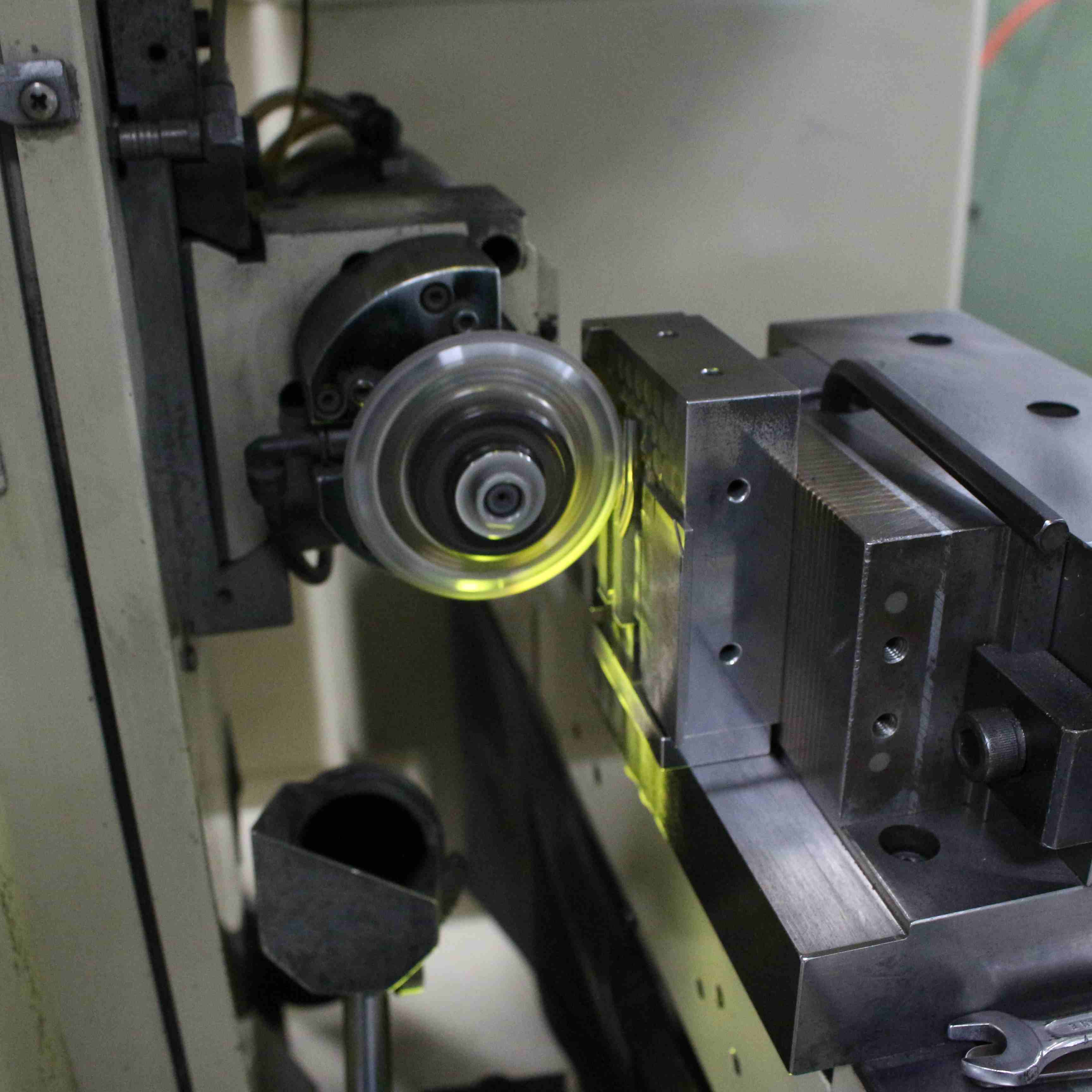
Before AI-powered simulation became mainstream, die design and stamping process optimization faced significant challenges. Engineers would design dies based on past experience, create physical prototypes, test them on stamping equipment, and then make adjustments based on the results. This cycle—design, prototype, test, revise—could repeat multiple times, especially for complex die parts used in automotive, electronics, or medical applications.   Not only is this process time-consuming (often taking weeks or even months for a single die), but it also carries high costs. Physical prototypes require materials, labor, and machine time, and each revision adds to the overall expense. Additionally, human intuition, while valuable, is prone to oversight—factors like material springback, die wear, and stress distribution can be difficult to predict accurately, leading to defects in the final product or premature die failure. For high-volume production, even small inefficiencies in die design or stamping processes can translate to significant financial losses. How AI-Powered Simulation Changes the Game AI-powered simulation combines the power of finite element analysis (FEA) with machine learning (ML) algorithms to create a virtual environment where engineers can design, test, and optimize die parts and stamping processes—all without physical prototypes. Unlike traditional simulation tools, which require manual input and interpretation, AI-driven solutions can learn from data, adapt to different scenarios, and provide actionable insights that human engineers might miss.   1. Predictive Accuracy for Complex Scenarios One of the biggest advantages of AI-powered simulation is its ability to predict complex stamping behaviors with unprecedented accuracy. AI algorithms analyze vast amounts of historical data—including material properties, die geometries, stamping parameters, and past performance—to identify patterns and correlations. This allows the simulation to predict how a die will perform under different conditions, such as changes in material thickness, stamping speed, or tool pressure.   For example, springback—a common challenge in stamping, where the material rebounds after being formed—is notoriously difficult to predict with traditional methods. AI-powered simulation can model springback with precision, allowing engineers to adjust die design (such as adding compensation features) before the die is ever manufactured. This eliminates the need for costly post-production adjustments and reduces the risk of defective parts. 2. Reduced Lead Times and Costs By replacing physical prototyping with virtual testing, AI-powered simulation cuts down lead times dramatically. What once took weeks can now be done in days or even hours. Engineers can test multiple die designs and stamping parameters in the virtual environment, compare results, and select the optimal solution—all without wasting materials or machine time. This not only speeds up the design-to-production cycle but also reduces costs associated with prototyping, rework, and scrap.   For small to medium-sized manufacturers, in particular, this is a game-changer. AI-powered simulation levels the playing field, allowing them to compete with larger companies by reducing their time-to-market and improving efficiency—without the need for massive investments in physical testing equipment.   3. Proactive Process Optimization AI-powered simulation doesn’t just help with die design—it also optimizes the entire stamping process. ML algorithms can analyze real-time data from stamping machines (such as force, temperature, and vibration) to identify potential issues before they cause defects or machine downtime. For example, the simulation can predict when a die is likely to wear out, allowing manufacturers to schedule maintenance proactively rather than reacting to a breakdown.   Additionally, AI can optimize stamping parameters (such as feed rate, pressure, and temperature) in real time, ensuring consistent quality across high-volume production runs. This is especially critical for industries like automotive and medical, where zero defects are required.   Real-World Applications in Metal Stamping Die Manufacturing The impact of AI-powered simulation is already being felt across the industry. For example, a leading automotive die manufacturer recently implemented an AI-driven simulation tool to design dies for electric vehicle (EV) battery components. The tool predicted springback and material flow with 95% accuracy, reducing the number of physical prototypes by 70% and cutting lead times by 40%. As a result, the manufacturer was able to meet tight EV production deadlines and reduce costs by 35% per die.   Another example comes from the medical device industry, where precision is paramount. A manufacturer of micro-stamped medical components used AI-powered simulation to optimize die design for tiny, complex parts. The simulation helped identify potential stress points that could lead to part failure, allowing engineers to adjust the die geometry and stamping parameters. This resulted in a 99.8% defect-free production rate, up from 92% before implementing the tool.   The Future of AI in Die Design and Stamping As AI technology continues to advance, its impact on die design and stamping process optimization will only grow. Future developments will likely include more advanced ML algorithms that can learn from real-time production data to continuously improve simulation accuracy, as well as integration with other Industry 4.0 technologies like digital twins and IoT sensors. This will create a fully connected, intelligent manufacturing ecosystem where die design, stamping, and maintenance are all optimized automatically.   For manufacturers who adopt AI-powered simulation, the benefits are clear: faster time-to-market, lower costs, higher quality, and a competitive edge in an increasingly crowded industry. Those who fail to embrace this technology risk falling behind, as customers demand more precise, cost-effective die parts and shorter lead times.   AI-powered simulation is not just a trend—it’s a transformative technology that is redefining how metal stamping die parts are designed and manufactured. By eliminating trial-and-error, improving predictive accuracy, and reducing lead times and costs, AI-driven simulation is helping manufacturers overcome the limitations of traditional methods and achieve new levels of efficiency and quality. As the industry continues to evolve, AI will become an essential tool for any manufacturer looking to stay ahead in the competitive world of metal stamping die parts production.  
  • Precision Stamping Mold Parts Tolerance Standards: Industry-General Dimensional Datums
    Precision Stamping Mold Parts Tolerance Standards: Industry-General Dimensional Datums Apr 29, 2026
    In precision manufacturing, even minor deviations can cause costly failures or poor assembly. Tolerance standards and dimensional datums are critical for reliable precision stamping mold performance, enabling consistent, high-quality components for automotive, aerospace, electronics.   What Are Tolerance Standards for Precision Stamping Mold Parts? Tolerance standards define allowable variations in mold part size, shape, and position, ensuring seamless functionality and interchangeability. Unlike general stamping, precision stamping requires tight tolerances—typically ±0.001 to ±0.005 inches (±0.025 to ±0.127 mm)—rooted in industry consensus, material behavior, and end-product needs.   These standards balance two key goals: ensuring part interchangeability (for easy batch/manufacturer swaps) and balancing precision with manufacturability, avoiding overly tight tolerances that inflate costs unnecessarily.   Industry-General Dimensional Datums: The Foundation of Tolerance Control Dimensional datums are reference points/lines/planes that standardize tolerance measurements. Without clear datums, precise tolerances become meaningless, leading to misalignment and non-conforming parts. The industry uses a “datum reference frame (DRF)” with three primary datums:   1. Primary Datum (Datum A) The most critical reference (often a flat surface like the mold’s parting surface or base plate bottom), ensuring alignment with the stamping press. It constrains three degrees of freedom (X/Y/Z translation) and sets the baseline for all measurements.   2. Secondary Datum (Datum B) Perpendicular to the primary datum, constraining two more degrees of freedom (X/Y rotation). Typically a side surface, slot, or pin (e.g., a punch shank’s side) to reinforce orientation relative to Datum A.   3. Tertiary Datum (Datum C) Perpendicular to both primary and secondary datums, constraining the final degree of freedom (Z rotation). A small feature (e.g., hole, notch) that fine-tunes position, ensuring full part constraint. Key Industry Standards Governing Tolerances and Datums Global standards provide a common language for manufacturers, ensuring supply chain consistency and clear design communication:   1. ASME Y14.5 (GD&T) The gold standard for geometric dimensioning and tolerancing (GD&T), establishing symbols and rules for part features. Updated in 2018 (reaffirmed 2024), it emphasizes datums for controlling geometric tolerances and is widely used in automotive, aerospace, and electronics.   2. ISO 2768 (General Tolerances) Defines general tolerances for unmarked linear/angular/geometric features, with four classes (F/M/C/V). Most precision mold parts use fine/medium classes, simplifying drawings by reducing redundant tolerance marking. 3. DIN 6930 (Stamped Steel Parts) Tailored for stamped steel, accounting for sheared metal behaviors (e.g., die roll) that affect tolerances. It specifies four accuracy levels for dimensions, concentricity, and symmetry, popular in European automotive/industrial sectors.   4. ISO 8062-3 (Moulded Parts) Focuses on dimensional/geometrical tolerances for moulded parts (including precision stamping molds), defining grades and machining allowances for global consistency.   Common Tolerance Ranges for Precision Stamping Mold Parts Typical ranges balance precision and cost, varying by part function, material, and process: Punches and Dies: Critical surfaces (punch tips, die cavities): ±0.001–±0.005 inches (±0.025–±0.127 mm); non-critical: ±0.005–±0.010 inches (±0.127–±0.254 mm). Guide Pins and Bushings: Diameter/concentricity: ±0.0005–±0.001 inches (±0.0127–±0.0254 mm); clearance: 0.0005–0.001 inches to avoid binding. Mold Bases: Mounting/datum surfaces: ±0.001–±0.002 inches (±0.0254–±0.0508 mm) for press alignment. Blanking/Piercing: Blanking: ±0.05 mm; piercing: ±0.05 mm (diameter/position); precision stamping reduces to ±0.025 mm. Factors Influencing Tolerance Selection Tolerance selection requires balancing four key factors:  End-Product Function: Critical/safety-critical parts (medical/aerospace) need tighter tolerances (often ±0.001 inches) than non-critical components.  Material Properties: Softer materials (aluminum, copper) hold tolerances better than hard materials (high-strength steel), which may require die compensation for springback.  Manufacturing Process: Progressive dies and servo presses enable tighter tolerances; tight-clearance dies (5–10% of material thickness) improve control. Cost: Tolerances tighter than ±0.001 inches require specialized tooling and temperature control, driving up costs exponentially.   In summary, understanding industry-general dimensional datums and tolerance standards is essential for optimizing precision stamping mold performance, reducing waste, and ensuring end-product quality. By adhering to established standards like ASME Y14.5 and ISO 2768, and carefully balancing functional needs with manufacturability, manufacturers can create reliable, cost-effective mold parts that meet the demands of today’s precision-driven industries. As technology advances, these standards will continue to evolve, but their core purpose—providing a consistent, reliable framework for tolerance control—will remain the cornerstone of precision stamping manufacturing.    
  • Differences between Blanking, Bending, and Drawing Dies
    Differences between Blanking, Bending, and Drawing Dies Apr 27, 2026
    Hardware stamping dies are the essential tools in metal forming, with blanking dies, bending dies, and drawing dies being the most widely used types. Although all three belong to the stamping die category, they differ significantly in structural design, working principles, and application scenarios. Accurately distinguishing their characteristics is the key to ensuring stamping quality.   Blanking Die:    The primary function of a blanking die is to separate material, serving as a typical example of a shearing die. It is mainly used to obtain the external profile of a part and forms the basic operation die in stamping processes. The main components include the punch, die (matrix), stripper mechanism, and locating parts. The cutting edges of the punch and die must fit precisely, with strict clearance control to avoid material tearing or excessive burrs. In operation, the press drives the punch down to cut the material along a closed contour, separating it from the stock. The separated workpiece may be a finished part or semi-finished product, while scrap is discharged through the die. Blanking dies have relatively simple structures, often using guide posts and bushings for precision. They are widely used for manufacturing flat parts like shims and flanges, and are ideal for mass production.   Bending Die:    The core function of a bending die is to plastically deform sheet material, forming workpieces with specific angles and shapes. Its structure mainly consists of the punch (upper die) and the die (lower die). The punch tip profile determines the inner geometry of the bend, while the die usually features a V-groove to support the sheet and define the outer bend contour. Some dies are also equipped with positioning stops to ensure bending accuracy. During operation, the sheet is positioned between the punch and die; the punch then presses down, causing the sheet to bend along the desired line. By carefully controlling pressure and punch-die clearance, cracks or springback are avoided. Bending dies can be designed with various punch and die profiles to accommodate different shapes, and are commonly used for processing brackets, connectors, and other angled parts.       Drawing Die:    Drawing dies are used for forming flat blanks into open, hollow components, with the key being control of material flow to avoid wrinkling or cracking. In addition to the punch and die, drawing dies feature a critical component: the blank holder (binder). The blank holder applies uniform pressure to prevent edging from wrinkling during forming and ensures smooth material flow into the die cavity. During operation, the punch presses the blank into the die cavity, causing plastic deformation and forming the hollow part. Drawing dies place stringent requirements on punch and die radii, clearance, and blank holder force control. They are often used for processing hollow products such as stainless steel kitchenware and automotive components. Complex parts usually require multiple drawing steps.     Blanking dies focus on material separation; Bending dies focus on angular plastic deformation; Drawing dies focus on hollow deep drawing forming. Each die type has a structure optimized for its core function and targeted application fields. Mastering these differences allows proper die selection, improves stamping efficiency and product consistency, and meets diversified processing demands of hardware stamped parts.   Our company specializes in manufacturing precision spare parts for all kinds of stamping dies, with over 19 years of professional experience in researching, developing and producing core components for blanking dies, bending dies and drawing dies. Over the past nearly two decades, we have focused on the core needs of stamping die manufacturing, focusing on key parts such as punch, die (matrix), stripper, blank holder, upper die, lower die and die cavity, and have accumulated rich technical experience and mature production processes. We adhere to the principle of "precision first, quality win", adopt advanced numerical control processing equipment and strict quality inspection systems, from raw material selection to finished product delivery, every link is strictly controlled to ensure that each component meets the high-precision requirements of stamping dies. Whether it is standard parts or customized components tailored to customer specific needs, we can provide reliable products and professional technical support. With our profound industry accumulation and customer-oriented service concept, we have won the trust and recognition of numerous stamping die manufacturers at home and abroad, and become a reliable partner for enterprises in the hardware stamping industry to improve production efficiency and product quality.    
  • Processing Key Points of Small-Sized and Precision Parts for Electronic Stamping Molds
    Processing Key Points of Small-Sized and Precision Parts for Electronic Stamping Molds Apr 03, 2026
    In the fast-evolving global electronics industry, the demand for miniaturization, high precision, and reliability of electronic products (e.g., smart wearables, automotive electronics) is rising. This drives the upgrading of electronic stamping mold technology, especially small-sized and precision mold parts—core components determining stamping product quality and service life. These small parts (≤5mm, tolerance ±0.01mm) rely on strict process control and advanced technologies to achieve ultra-high precision. Material Selection: The Foundation of Precision and Durability The material of small precision stamping mold parts directly affects their processability, wear resistance, and service life. Unlike traditional stamping molds, electronic mold parts endure high-frequency stamping (thousands of times per hour) and must maintain dimensional stability. Thus, material selection follows the principle of "high precision, hardness, processability, and stability." Common materials and their applications:   High-speed steel (HSS): Widely used for small punches, dies, and guides, offering good wear resistance, machinability, and heat treatment performance. It reaches HRC 62-65 after heat treatment, meeting general electronic mold requirements.   Cemented carbide: Preferred for ultra-precise parts (e.g., micro punches), with hardness up to HRC 85-90 for superior wear resistance. Note its brittleness—handle carefully to avoid cracking. Stainless steel/special alloys: Ideal for harsh environments (high temperature, corrosion). SUS304, SUS316L, and alloys like titanium ensure reliability in complex conditions (e.g., automotive engines).   Key point: Inspect material uniformity, purity, and surface quality upfront. Internal defects (inclusions, cracks) and surface flaws (scratches, rust) cause precision deviations or mold failure.   Precision Machining: The Core of Dimensional Control Small precision electronic mold parts require strict dimensional, shape, and position accuracy—even 0.005mm deviations can fail stamping products. Ordinary machining is insufficient; advanced equipment and processes are needed, focusing on these key links:   Turning and Milling: Ensuring Basic Precision High-precision CNC turning/milling machines (±0.001mm positioning accuracy) process simple-shaped parts (shafts, sleeves, guide pins). Key points:   Clamping stability: Use precision fixtures to reduce deformation. For ultra-small parts (<1mm diameter), use vacuum/magnetic chucks to protect fragile parts and ensure batch consistency.   Cutting parameters: Use diamond/CBN tools for hard materials, reduce feed rates, and apply sufficient cooling to minimize thermal deformation— a major precision factor.   Dimensional inspection: Use micrometers/dial indicators for real-time checks. For ±0.005mm tolerances, use CNC-integrated online inspection to avoid waste.   Wire Electrical Discharge Machining (WEDM): Achieving Complex Shapes and High Precision Complex-shaped parts (micro holes ≤0.1mm, narrow slots ≤0.05mm) rely on WEDM (especially slow wire), which offers high precision, good surface quality, and no cutting force. Key points: Key WEDM process points:    Electrode wire: Use uniform, high-tensile molybdenum/copper wire. Match diameter to part size (down to 0.02mm for ultra-micro parts) to avoid breakage and ensure contour accuracy.   Parameter setting: Adjust pulse width, interval, and current by material/precision. For hard materials, use small pulse width/low current to reduce thermal deformation; slow wire achieves Ra ≤ 0.02μm.   Fixture positioning: Use precision fixtures (pins, V-blocks) for accurate part positioning. For complex parts, use CNC positioning to boost accuracy and efficiency.   Grinding and Polishing: Improving Surface Quality and Precision Post-turning/milling/WEDM, tiny burrs/tool marks affect mold assembly and stamping quality. Grinding and polishing are essential finishing steps:   Precision grinding: Use high-precision grinders to ensure flatness/parallelism. For small/thin-walled parts, use micro-grinding to avoid deformation.   Polishing: Follow "coarse-to-fine" with 1000#-5000# abrasives to reach Ra ≤ 0.01μm. Use uniform force to avoid uneven surfaces. For ≤0.005mm burrs, use plasma/electrochemical deburring.     With a steadfast focus on the field of electronic connectors, Hongyu Mould is fully dedicated to the professional production and manufacturing of stamping mold parts, adhering to the above-mentioned precision processing standards to provide high-quality, reliable products for the electronic industry.  
  • High-Precision Stamping Dies: Hidden Ingenuity in Every Millimeter
    High-Precision Stamping Dies: Hidden Ingenuity in Every Millimeter Mar 27, 2026
    In industrial manufacturing, a difference of just 0.001mm can lead to poor contact in electronic connectors, reduced lifespan of automotive molds, or inaccurate precision in medical devices. High-precision stamping die components are the creators behind these “millimeter-level miracles”—delivering exceptional accuracy and stability to uphold the quality bottom line for industries such as electronics, automotive, and healthcare.   Precision: The “Lifeline” of Precision Manufacturing    The core of high-precision stamping dies lies in the ultimate control of micron-level errors: Forming Dimensions : The minimum forming size can reach 0.014mm (with some inductor molds even achieving stacking precision of 0.002mm), and fitting clearances are controlled within 0.002mm, ensuring a perfect fit even after millions of stamping cycles.   Surface Quality : Through mirror polishing, optical profile grinding, and other processes, a mirror-level surface roughness of Ra0.03 is achieved (equivalent to 1/2000 the diameter of a human hair), greatly reducing the risk of part wear and sticking.   Geometric Tolerances : Flatness and parallelism tolerances can be as tight as 0.0005mm, with combined tolerances of 0.01mm, allowing even complex mold assemblies to fit together with precision.     Stability: The “Ballast” of Mass Production    Beyond precision, stability is the other cornerstone of high-precision molds. hongyu Precision ensures “consistency as new, even after thousands of cycles” with three key safeguards:   Material Selection : Utilization of tungsten steel, ceramics, and medical-grade safe materials balances hardness, wear resistance, and bio-compatibility (for medical use).   Closed-Loop Processes : From EDM (with minimum chamfer R0.04mm), contour grinding, to welding and assembly, every process is equipped with both optical inspection and coordinate measuring, ensuring zero defects leave the facility.   Comprehensive Quality Control: A full life-cycle management system from raw material intake to finished product delivery covers “material–processing–inspection–after-sales,” eliminating concerns about batch variations for our clients.   Hongyu Precision: Your All-in-One Partner in Precision Manufacturing    With over ten years’ expertise in high-precision stamping die component manufacturing, Dongguan hongyu Precision Technology Co., Ltd. (hongyu Precision) delivers one-stop solutions centered on “full-scenario adaptability and customized service.”   Product Portfolio : Products cover electronic connector molds, motor stator and rotor molds, sensor molds, ceramic components, can-end mold assemblies, and more—serving a wide range of industries including electronics, automotive, healthcare, and packaging.   Technical Empowerment : We support personalized requirements such as special-shaped punches, specialized coatings, non-standard mold assemblies, all while adhering to ISO international standards, balancing “efficiency through standardization” with “flexibility through customization.”   Service Philosophy : From requirement analysis through after-sales maintenance, we respond to client needs at every step. Our “efficient, professional, and innovative” approach makes us a reliable manufacturing backbone for customers around the globe.     On the road of high-precision mold parts manufacturing, hongyu Precision continues to “write the answer to industrial quality in every millimeter, with precision as the pen and stability as the ink.” Whether you are an electronics manufacturer in pursuit of extreme precision or an automotive enterprise seeking stable, long-term supply, hongyu Precision is ready to be your trustworthy precision partner, leveraging a decade of technical expertise to help you upgrade your manufacturing capabilities.    
  • How Heat Treatment of Mold Steels Shapes Machining Precision
    How Heat Treatment of Mold Steels Shapes Machining Precision Mar 20, 2026
    In precision mold making, heat treatment is not just about hardness—it directly defines dimensional stability, machinability, and final part accuracy. Even the best CNC machining will fail to hold tight tolerances if heat treatment induces unexpected distortion, residual stress, or uneven microstructure.   Why Heat Treatment Matters for Mold Parts   Mold steels such as P20, H13, SKD61, DC53, Cr12MoV rely on heat treatment to achieve: · Sufficient hardness and wear resistance   · Strength under cyclic load and temperature   · Dimensional stability over millions of cycles   But these benefits come with physical changes that directly impact machining accuracy: volume change, phase transformation, thermal stress, and residual stress.   Key Ways Heat Treatment Affects Machining Precision   1. Dimensional Distortion & Volume Change   Phase transformations during quenching and tempering change the specific volume of steel. · Parts may expand, shrink, bend, or twist   · Holes close, shafts grow, flat surfaces warp   · Typical distortion ranges: 0.05%–0.5% — enough to ruin precision fits   This is why high-precision mold parts are never finished to final size before heat treatment. A machining allowance (stock) must be reserved for post-heat-treatment finishing.   2. Residual Stress Ruins Stability   · Quenching creates extreme internal stress   · Stress relief is critical: untempered parts warp or crack during finish machining   · Residual stress also leads to in-service deformation, destroying longterm precision   Best practice: · Stress relieving after rough machining   · Full tempering immediately after quenching   3. Hardness Uniformity & Machinability   Uneven heat treatment causes:   · Soft spots that lead to chatter, vibration, and poor surface finish   · Hard spots that wear tools quickly and break dimensional consistency   · Inconsistent EDM and polishing results   Uniform hardness = predictable machining = stable precision. Heat Treatment Workflow for Maximum Precision   Follow this sequence to protect accuracy:   1. Stress relief after rough machining   2. Quench + prompt temper to stabilize structure   3. Semi-finish machining with small allowance   4. Optional cryogenic treatment for ultra-stability   5. Final finish machining to tight tolerances   For ultra-precision molds, vacuum heat treatment is strongly recommended:   · Minimizes oxidation and decarburization   · Reduces distortion to <0.001 mm   · Preserves fine surface quality for finishing   Material-Specific Notes   · Pre-hardened steels (P20):Good stability, minimal in-process distortion   · Hot-work steels (H13, SKD61):Sensitive to cooling rate; use marquenching to reduce warpage   · High-chromium tool steels (DC53, Cr12MoV):High distortion risk; must use multiple tempers and slow cooling   Heat treatment is the foundation of precision in mold components. It does not just improve performance—it determines whether your parts stay within tolerance during machining, assembly, and use.   By controlling heating/cooling rates, reducing residual stress, using vacuum processes, and planning machining allowances, you can turn heat treatment from a risk into a precision advantage.   If you work with tight-tolerance mold bases, core pins, or inserts—never skip proper heat treatment planning.
  • EDM Wire Cutting for Complex Tungsten Carbide Shapes: Key Steps to Avoid Overcutting
    EDM Wire Cutting for Complex Tungsten Carbide Shapes: Key Steps to Avoid Overcutting Feb 11, 2026
    Tungsten carbide stands as one of the most widely used ultra-hard materials in modern manufacturing, prized for its exceptional wear resistance, high compressive strength, and dimensional stability under extreme operating conditions. For complex, tight-tolerance components—such as custom dies, precision inserts, micro-tools, and contoured mechanical parts—wire EDM (electrical discharge machining) is the one of the most effective processing method, as traditional cutting tools cannot machine tungsten carbide efficiently or accurately. However, a persistent challenge plagues even experienced fabricators: overcutting, which degrades part precision, ruins surface finish, wastes high-cost tungsten carbide blanks, and leads to costly reworks or scrapped parts.   When working with intricate, non-linear, or small-feature tungsten carbide shapes, overcutting is not just a minor error—it can invalidate the entire component. Unlike general steel or alloy machining, tungsten carbide's high hardness and brittleness amplify the risks of EDM overcut, making process control absolutely critical.   Optimize Wire Electrode Selection & Tension Control   The foundation of error-free wire EDM starts with the wire itself. For hard, brittle tungsten carbide, avoid standard brass wires for fine finishing passes; instead, use stratified wires, coated wires, or high-tensile-strength molybdenum wires designed for hard-alloy machining. These wires maintain stable discharge energy, reduce wire vibration, and minimize lateral deflection—one of the top causes of unintended overcut in tight corners and complex curves.   Equally important is constant, precise wire tension. Fluctuating tension causes the wire to sway mid-cut, especially in deep or narrow kerfs common in complex tungsten carbide parts. Modern closed-loop tension systems maintain steady force throughout the cut, preventing the wire from drifting and creating oversized dimensions. For micro-complex shapes, set tension to the manufacturer's recommended range for hard materials, never exceeding safe limits to avoid wire breakage.   Fine-Tune Discharge Parameters (Pulse Settings) for Tungsten Carbide   EDM overcut is directly tied to uncontrolled spark energy and pulse duration. Tungsten carbide requires a low-erosion, high-precision parameter set—not the aggressive settings used for soft metals. Overly strong pulses create larger craters, widen the kerf, and push the wire off-path, resulting in consistent overcut across complex geometries.   To mitigate this:   • Use short pulse-on times and long pulse-off times for finishing passes, limiting spark size and heat input.   • Reduce peak current in semi-finishing and finishing stages to minimize thermal expansion and wire deflection.   • Program adaptive parameter control for corner and radius sections—complex tungsten carbide parts often have sharp internal corners and tight radii, where standard parameters cause excessive overcut. Corner slowdown and power reduction ensure the wire follows the exact toolpath without over-eroding.   Strict Toolpath Programming & Compensation Logic   Poor CAM programming is a leading cause of overcut in complex shapes. For tungsten carbide components, wire radius compensation must be applied accurately, and toolpaths must account for kerf width specific to hard-material EDM. Generic compensation values designed for steel will fail on tungsten carbide, leading to consistent undersize or oversize cuts.     Additional best practices:   • Avoid sharp, sudden direction changes in the toolpath; use smooth transition arcs to reduce wire shake.   • Add multiple skim passes (2–4 passes minimum for complex profiles) instead of relying on a single cut—roughing removes bulk material, while successive skim passes correct dimensional drift and eliminate overcut entirely.   • Simulate the full toolpath in CAM software before cutting to detect collisions, path deviations, or compensation errors that could cause overcut in hard-to-reach features.   Stable Workholding & Vibration Damping   Tungsten carbide blanks are dense and rigid, but poor fixturing introduces movement or misalignment during cutting—even micrometers of shift translate to visible overcut in precision parts. Use custom, low-deformation workholding fixtures, and secure the blank evenly to avoid clamping stress that distorts the material or shifts position mid-process.   Vibration from the machine or surrounding environment also disrupts wire alignment. Isolate the EDM machine from floor vibration, and ensure the worktable, chuck, and wire guides are fully calibrated and rigid. For deep-profile complex parts, use support fixtures to prevent blank chatter, which is a hidden cause of uneven overcut along vertical or angled surfaces.   Accurate Machine Calibration & Maintenance   Even the best programming and parameters cannot overcome a poorly calibrated EDM machine. Regular calibration of wire guides, axis positioning, encoder feedback, and dielectric fluid flow is non-negotiable for tungsten carbide precision machining. Worn or misaligned wire guides cause the wire to run off-center, creating consistent overcut across all features—replace guides at recommended intervals and verify alignment daily for high-precision jobs.   Dielectric fluid quality also impacts cut stability. Clean, deionized dielectric fluid ensures stable, predictable sparks; contaminated fluid causes erratic discharges, widens the kerf unpredictably, and leads to random overcut in complex geometries. Maintain fluid conductivity levels and filtration efficiency to preserve process stability.   Thermal Stability Control   Tungsten carbide has low thermal conductivity, but EDM's localized heat can still cause minor thermal expansion—enough to create overcut in micron-tolerance complex parts. Maintain a consistent ambient temperature around the EDM machine, avoid drafty areas, and allow the blank to reach thermal equilibrium with the machine before cutting. For long-duration cuts on complex tungsten carbide shapes, program periodic pauses to dissipate residual heat and prevent dimensional drift.     Why Overcut Prevention Matters for Tungsten Carbide   Tungsten carbide is an expensive, high-performance material, and scrap parts directly impact production costs and lead times. Complex shapes demand absolute dimensional accuracy—often within ±0.002mm or tighter—leaving no room for overcutting. By following the steps above, fabricators can achieve repeatable, burr-free, precision cuts while maximizing material utilization and part integrity.   Partner with a Trusted Expert for Precision Wire EDM   Achieving perfect, overcut-free wire EDM for complex tungsten carbide shapes requires more than just technical know-how—it demands top-tier machinery, decades of processing experience, and an uncompromising focus on precision.   Hongyu Company specializes in high-precision wire EDM machining, with a core focus on complex tungsten carbide components and ultra-hard material processing. Equipped with advanced, fully automated wire EDM equipment(like AGIE CHARMILLES, Seibu and Sodic), closed-loop control systems, and professional technical teams, we deliver industry-leading dimensional accuracy, smooth surface finishes, and zero-defect processing for even the most intricate profiles. Our strict process control and dedicated focus on EDM optimization ensure zero overcutting, consistent quality, and reliable performance for every tungsten carbide part we produce.     For all your precision wire EDM needs—from complex contours to micro-tolerance tungsten carbide components—Hongyu Company is your trusted partner for accuracy, efficiency, and excellence.You can send your product requirements to our email address chunhe@dghongyumold.com, and we will provide you with the most professional solution within 24 hours.
1 2 3

A total of3pages

Need Help? Chat with us

leave a message
For any request of information or technical support, fill in the form. All fields marked with an asterisk* are required.
Submit
Looking for FAQs?
Contact us #
+86 769 832011519

Our hours

Mon 11/21 - Wed 11/23: 9 AM - 8 PM
Thu 11/24: closed - Happy Thanksgiving!
Fri 11/25: 8 AM - 10 PM
Sat 11/26 - Sun 11/27: 10 AM - 9 PM
(all hours are Eastern Time)

home

products

whatsApp

Contacts