banner
  • Tolerance Control for Stamping Die Parts: 5 Key Points
    Tolerance Control for Stamping Die Parts: 5 Key Points Aug 21, 2026
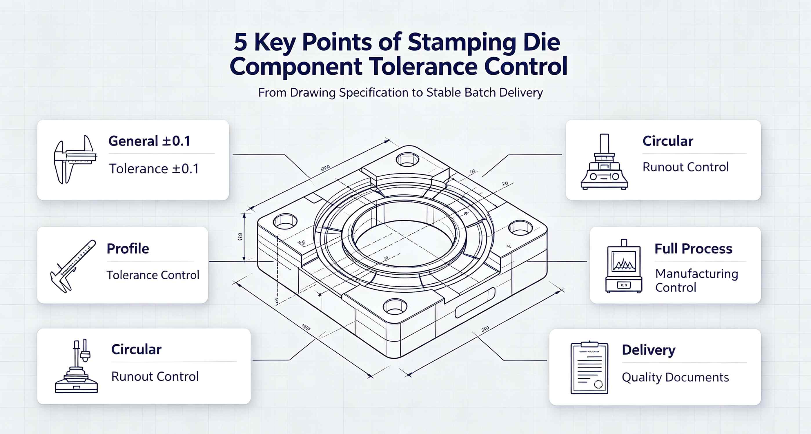
    In the stamping die industry, tolerance control is the core factor determining tool life and product quality. When sourcing die components, buyers from the automotive and home appliance sectors in Europe and North America first evaluate a supplier's understanding and execution of tolerances. This article breaks down 5 key dimensions to help you master tolerance control for stamping die parts. 1. Understanding "General Tolerance ±0.1"   Many drawings specify "General tolerance ±0.1" in the title block or general notes. However, this does not mean all dimensions can be machined to ±0.1. Scope: Applies only to linear and angular dimensions without individual tolerance callouts. Exceptions: Mating surfaces, functional surfaces, and locating dimensions typically have tighter tolerances (e.g., ±0.01 or +0.005). Industry Standards: ISO 2768-m (medium class) corresponds to ±0.1; ISO 2768-f (fine class) corresponds to ±0.05. Tip for Buyers: Always check the general tolerance grade in the title block first, then look for any special tolerance callouts. Combining both gives you the true precision requirement of the part.   2. Geometric Tolerance: Profile of a Surface    Profile of a Surface (symbol ⌒) is one of the most common geometric tolerances in stamping dies. It controls the shape accuracy of curved surfaces or complex contours. Typical Callout: ⌒ 0.01 A (Profile 0.01 mm relative to Datum A) Processing Challenge: High-profile requirements often demand CNC grinding or EDM (Electrical Discharge Machining) rather than simple milling. Inspection Method: CMM (Coordinate Measuring Machine) or profilometer. Key Point: The smaller the profile tolerance, the better the interchangeability of die parts and the more consistent the stamped parts will be. 3. Geometric Tolerance: Circular Runout   Circular Runout (symbol ↙) primarily controls the concentricity of rotating parts such as punches, guide pins, and rollers. Typical Callout: ↙ 0.01 A (Circular Runout 0.01 mm relative to Datum A) Key Influencing Factors: Clamping eccentricity Thermal deformation during grinding Quality of center holes Process Assurance: Using two-center mounting + multiple finish grinding passes can reliably control runout within 0.01 mm. Common Misconception: Circular runout is not the same as coaxiality. Runout is a composite error (including roundness, coaxiality, and axis straightness), making it a stricter requirement.   4. How to Ensure Consistency Through Process Control Tolerance control goes beyond drawing annotations — it must be strictly executed throughout the manufacturing process. ① Material Pre-treatment Steel should undergo stress-relief annealing before rough machining to eliminate internal stresses and reduce subsequent deformation. For high-precision parts (punches, insert cavities), vacuum heat treatment is recommended to control distortion within 0.02 mm. ② In-Process Inspection Perform first-article inspection on critical dimensions after each operation. Adjust parameters immediately if deviations are found. For batch production, use SPC (Statistical Process Control) to monitor dimensional trends and detect drift early. ③ Environmental Control Precision grinding workshops should maintain a constant temperature of 20±2°C to avoid thermal expansion errors. Before measurement, allow parts to stabilize in the temperature-controlled room for at least 2 hours. 5. Quality Documentation for Delivery   European and American customers typically require the following documents upon delivery: Inspection Certificate: Lists actual measured values for all critical dimensions, compared against drawing tolerances. Geometric Tolerance Report: Actual data for profile, runout, and other GD&T requirements. Material Certificate: Chemical composition and heat treatment records for the steel used. One-Sentence Summary: Tolerance control is not about "whether you can do it once," but "whether you can reproduce it consistently." Suppliers with robust process control and inspection systems are the ones worth long-term partnerships. Summary Table Key Point Core Content Buyer Priority General Tolerance ±0.1 Understand scope; distinguish from special tolerances ⭐⭐⭐ Profile Control Surface accuracy; impacts stamped part consistency ⭐⭐⭐⭐ Runout Control Concentricity of rotating parts; affects die life ⭐⭐⭐⭐ Process Consistency Full-cycle control: material, inspection, environment ⭐⭐⭐⭐⭐ Delivery Documents Inspection reports, material certificates ⭐⭐⭐   Looking for a reliable stamping die parts supplier? Contact us today. We offer one-stop service from drawing interpretation and process design to final inspection — ensuring every part meets your tolerance requirements.
  • Processing Key Points of Small-Sized and Precision Parts for Electronic Stamping Molds
    Processing Key Points of Small-Sized and Precision Parts for Electronic Stamping Molds Apr 03, 2026
    In the fast-evolving global electronics industry, the demand for miniaturization, high precision, and reliability of electronic products (e.g., smart wearables, automotive electronics) is rising. This drives the upgrading of electronic stamping mold technology, especially small-sized and precision mold parts—core components determining stamping product quality and service life. These small parts (≤5mm, tolerance ±0.01mm) rely on strict process control and advanced technologies to achieve ultra-high precision. Material Selection: The Foundation of Precision and Durability The material of small precision stamping mold parts directly affects their processability, wear resistance, and service life. Unlike traditional stamping molds, electronic mold parts endure high-frequency stamping (thousands of times per hour) and must maintain dimensional stability. Thus, material selection follows the principle of "high precision, hardness, processability, and stability." Common materials and their applications:   High-speed steel (HSS): Widely used for small punches, dies, and guides, offering good wear resistance, machinability, and heat treatment performance. It reaches HRC 62-65 after heat treatment, meeting general electronic mold requirements.   Cemented carbide: Preferred for ultra-precise parts (e.g., micro punches), with hardness up to HRC 85-90 for superior wear resistance. Note its brittleness—handle carefully to avoid cracking. Stainless steel/special alloys: Ideal for harsh environments (high temperature, corrosion). SUS304, SUS316L, and alloys like titanium ensure reliability in complex conditions (e.g., automotive engines).   Key point: Inspect material uniformity, purity, and surface quality upfront. Internal defects (inclusions, cracks) and surface flaws (scratches, rust) cause precision deviations or mold failure.   Precision Machining: The Core of Dimensional Control Small precision electronic mold parts require strict dimensional, shape, and position accuracy—even 0.005mm deviations can fail stamping products. Ordinary machining is insufficient; advanced equipment and processes are needed, focusing on these key links:   Turning and Milling: Ensuring Basic Precision High-precision CNC turning/milling machines (±0.001mm positioning accuracy) process simple-shaped parts (shafts, sleeves, guide pins). Key points:   Clamping stability: Use precision fixtures to reduce deformation. For ultra-small parts (<1mm diameter), use vacuum/magnetic chucks to protect fragile parts and ensure batch consistency.   Cutting parameters: Use diamond/CBN tools for hard materials, reduce feed rates, and apply sufficient cooling to minimize thermal deformation— a major precision factor.   Dimensional inspection: Use micrometers/dial indicators for real-time checks. For ±0.005mm tolerances, use CNC-integrated online inspection to avoid waste.   Wire Electrical Discharge Machining (WEDM): Achieving Complex Shapes and High Precision Complex-shaped parts (micro holes ≤0.1mm, narrow slots ≤0.05mm) rely on WEDM (especially slow wire), which offers high precision, good surface quality, and no cutting force. Key points: Key WEDM process points:    Electrode wire: Use uniform, high-tensile molybdenum/copper wire. Match diameter to part size (down to 0.02mm for ultra-micro parts) to avoid breakage and ensure contour accuracy.   Parameter setting: Adjust pulse width, interval, and current by material/precision. For hard materials, use small pulse width/low current to reduce thermal deformation; slow wire achieves Ra ≤ 0.02μm.   Fixture positioning: Use precision fixtures (pins, V-blocks) for accurate part positioning. For complex parts, use CNC positioning to boost accuracy and efficiency.   Grinding and Polishing: Improving Surface Quality and Precision Post-turning/milling/WEDM, tiny burrs/tool marks affect mold assembly and stamping quality. Grinding and polishing are essential finishing steps:   Precision grinding: Use high-precision grinders to ensure flatness/parallelism. For small/thin-walled parts, use micro-grinding to avoid deformation.   Polishing: Follow "coarse-to-fine" with 1000#-5000# abrasives to reach Ra ≤ 0.01μm. Use uniform force to avoid uneven surfaces. For ≤0.005mm burrs, use plasma/electrochemical deburring.     With a steadfast focus on the field of electronic connectors, Hongyu Mould is fully dedicated to the professional production and manufacturing of stamping mold parts, adhering to the above-mentioned precision processing standards to provide high-quality, reliable products for the electronic industry.  
Need Help? Chat with us

leave a message
For any request of information or technical support, fill in the form. All fields marked with an asterisk* are required.
Submit
Looking for FAQs?
Contact us #
+86 769 832011519

Our hours

Mon 11/21 - Wed 11/23: 9 AM - 8 PM
Thu 11/24: closed - Happy Thanksgiving!
Fri 11/25: 8 AM - 10 PM
Sat 11/26 - Sun 11/27: 10 AM - 9 PM
(all hours are Eastern Time)

home

products

whatsApp

Contacts