banner
  • Tolerance Control for Stamping Die Parts: 5 Key Points
    Tolerance Control for Stamping Die Parts: 5 Key Points Aug 21, 2026
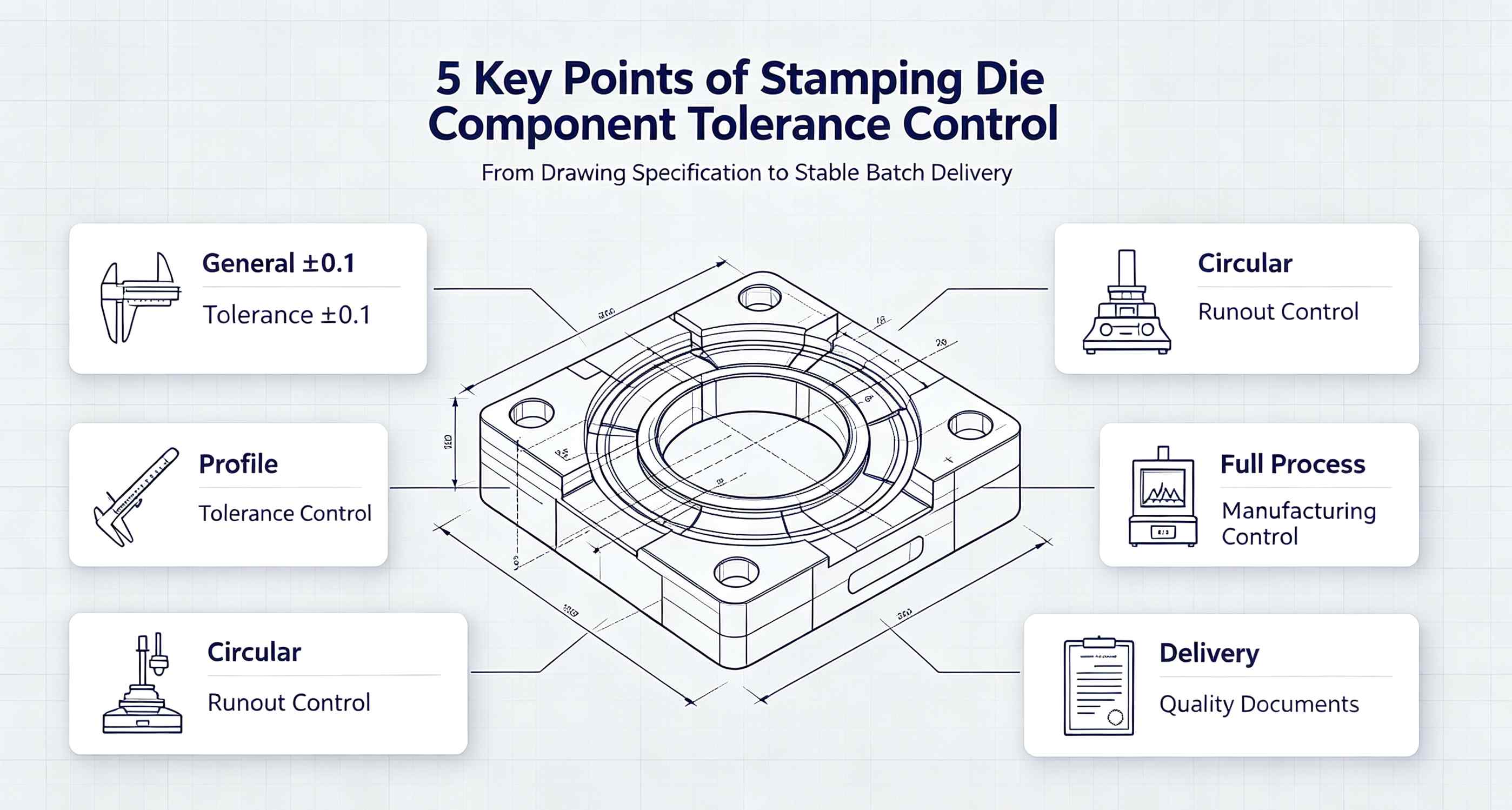
    In the stamping die industry, tolerance control is the core factor determining tool life and product quality. When sourcing die components, buyers from the automotive and home appliance sectors in Europe and North America first evaluate a supplier's understanding and execution of tolerances. This article breaks down 5 key dimensions to help you master tolerance control for stamping die parts. 1. Understanding "General Tolerance ±0.1"   Many drawings specify "General tolerance ±0.1" in the title block or general notes. However, this does not mean all dimensions can be machined to ±0.1. Scope: Applies only to linear and angular dimensions without individual tolerance callouts. Exceptions: Mating surfaces, functional surfaces, and locating dimensions typically have tighter tolerances (e.g., ±0.01 or +0.005). Industry Standards: ISO 2768-m (medium class) corresponds to ±0.1; ISO 2768-f (fine class) corresponds to ±0.05. Tip for Buyers: Always check the general tolerance grade in the title block first, then look for any special tolerance callouts. Combining both gives you the true precision requirement of the part.   2. Geometric Tolerance: Profile of a Surface    Profile of a Surface (symbol ⌒) is one of the most common geometric tolerances in stamping dies. It controls the shape accuracy of curved surfaces or complex contours. Typical Callout: ⌒ 0.01 A (Profile 0.01 mm relative to Datum A) Processing Challenge: High-profile requirements often demand CNC grinding or EDM (Electrical Discharge Machining) rather than simple milling. Inspection Method: CMM (Coordinate Measuring Machine) or profilometer. Key Point: The smaller the profile tolerance, the better the interchangeability of die parts and the more consistent the stamped parts will be. 3. Geometric Tolerance: Circular Runout   Circular Runout (symbol ↙) primarily controls the concentricity of rotating parts such as punches, guide pins, and rollers. Typical Callout: ↙ 0.01 A (Circular Runout 0.01 mm relative to Datum A) Key Influencing Factors: Clamping eccentricity Thermal deformation during grinding Quality of center holes Process Assurance: Using two-center mounting + multiple finish grinding passes can reliably control runout within 0.01 mm. Common Misconception: Circular runout is not the same as coaxiality. Runout is a composite error (including roundness, coaxiality, and axis straightness), making it a stricter requirement.   4. How to Ensure Consistency Through Process Control Tolerance control goes beyond drawing annotations — it must be strictly executed throughout the manufacturing process. ① Material Pre-treatment Steel should undergo stress-relief annealing before rough machining to eliminate internal stresses and reduce subsequent deformation. For high-precision parts (punches, insert cavities), vacuum heat treatment is recommended to control distortion within 0.02 mm. ② In-Process Inspection Perform first-article inspection on critical dimensions after each operation. Adjust parameters immediately if deviations are found. For batch production, use SPC (Statistical Process Control) to monitor dimensional trends and detect drift early. ③ Environmental Control Precision grinding workshops should maintain a constant temperature of 20±2°C to avoid thermal expansion errors. Before measurement, allow parts to stabilize in the temperature-controlled room for at least 2 hours. 5. Quality Documentation for Delivery   European and American customers typically require the following documents upon delivery: Inspection Certificate: Lists actual measured values for all critical dimensions, compared against drawing tolerances. Geometric Tolerance Report: Actual data for profile, runout, and other GD&T requirements. Material Certificate: Chemical composition and heat treatment records for the steel used. One-Sentence Summary: Tolerance control is not about "whether you can do it once," but "whether you can reproduce it consistently." Suppliers with robust process control and inspection systems are the ones worth long-term partnerships. Summary Table Key Point Core Content Buyer Priority General Tolerance ±0.1 Understand scope; distinguish from special tolerances ⭐⭐⭐ Profile Control Surface accuracy; impacts stamped part consistency ⭐⭐⭐⭐ Runout Control Concentricity of rotating parts; affects die life ⭐⭐⭐⭐ Process Consistency Full-cycle control: material, inspection, environment ⭐⭐⭐⭐⭐ Delivery Documents Inspection reports, material certificates ⭐⭐⭐   Looking for a reliable stamping die parts supplier? Contact us today. We offer one-stop service from drawing interpretation and process design to final inspection — ensuring every part meets your tolerance requirements.
  • Differences between Blanking, Bending, and Drawing Dies
    Differences between Blanking, Bending, and Drawing Dies Apr 27, 2026
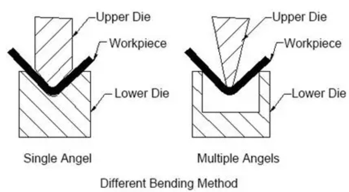
    Hardware stamping dies are the essential tools in metal forming, with blanking dies, bending dies, and drawing dies being the most widely used types. Although all three belong to the stamping die category, they differ significantly in structural design, working principles, and application scenarios. Accurately distinguishing their characteristics is the key to ensuring stamping quality.   Blanking Die:    The primary function of a blanking die is to separate material, serving as a typical example of a shearing die. It is mainly used to obtain the external profile of a part and forms the basic operation die in stamping processes. The main components include the punch, die (matrix), stripper mechanism, and locating parts. The cutting edges of the punch and die must fit precisely, with strict clearance control to avoid material tearing or excessive burrs. In operation, the press drives the punch down to cut the material along a closed contour, separating it from the stock. The separated workpiece may be a finished part or semi-finished product, while scrap is discharged through the die. Blanking dies have relatively simple structures, often using guide posts and bushings for precision. They are widely used for manufacturing flat parts like shims and flanges, and are ideal for mass production.   Bending Die:    The core function of a bending die is to plastically deform sheet material, forming workpieces with specific angles and shapes. Its structure mainly consists of the punch (upper die) and the die (lower die). The punch tip profile determines the inner geometry of the bend, while the die usually features a V-groove to support the sheet and define the outer bend contour. Some dies are also equipped with positioning stops to ensure bending accuracy. During operation, the sheet is positioned between the punch and die; the punch then presses down, causing the sheet to bend along the desired line. By carefully controlling pressure and punch-die clearance, cracks or springback are avoided. Bending dies can be designed with various punch and die profiles to accommodate different shapes, and are commonly used for processing brackets, connectors, and other angled parts.       Drawing Die:    Drawing dies are used for forming flat blanks into open, hollow components, with the key being control of material flow to avoid wrinkling or cracking. In addition to the punch and die, drawing dies feature a critical component: the blank holder (binder). The blank holder applies uniform pressure to prevent edging from wrinkling during forming and ensures smooth material flow into the die cavity. During operation, the punch presses the blank into the die cavity, causing plastic deformation and forming the hollow part. Drawing dies place stringent requirements on punch and die radii, clearance, and blank holder force control. They are often used for processing hollow products such as stainless steel kitchenware and automotive components. Complex parts usually require multiple drawing steps.     Blanking dies focus on material separation; Bending dies focus on angular plastic deformation; Drawing dies focus on hollow deep drawing forming. Each die type has a structure optimized for its core function and targeted application fields. Mastering these differences allows proper die selection, improves stamping efficiency and product consistency, and meets diversified processing demands of hardware stamped parts.   Our company specializes in manufacturing precision spare parts for all kinds of stamping dies, with over 19 years of professional experience in researching, developing and producing core components for blanking dies, bending dies and drawing dies. Over the past nearly two decades, we have focused on the core needs of stamping die manufacturing, focusing on key parts such as punch, die (matrix), stripper, blank holder, upper die, lower die and die cavity, and have accumulated rich technical experience and mature production processes. We adhere to the principle of "precision first, quality win", adopt advanced numerical control processing equipment and strict quality inspection systems, from raw material selection to finished product delivery, every link is strictly controlled to ensure that each component meets the high-precision requirements of stamping dies. Whether it is standard parts or customized components tailored to customer specific needs, we can provide reliable products and professional technical support. With our profound industry accumulation and customer-oriented service concept, we have won the trust and recognition of numerous stamping die manufacturers at home and abroad, and become a reliable partner for enterprises in the hardware stamping industry to improve production efficiency and product quality.    
Need Help? Chat with us

leave a message
For any request of information or technical support, fill in the form. All fields marked with an asterisk* are required.
Submit
Looking for FAQs?
Contact us #
+86 769 832011519

Our hours

Mon 11/21 - Wed 11/23: 9 AM - 8 PM
Thu 11/24: closed - Happy Thanksgiving!
Fri 11/25: 8 AM - 10 PM
Sat 11/26 - Sun 11/27: 10 AM - 9 PM
(all hours are Eastern Time)

home

products

whatsApp

Contacts