banner
  • Why "Wire EDM Profile Deviation ±0.002 mm" Is a Systems Engineering Challenge — Not Just a Machine Spec
    Why "Wire EDM Profile Deviation ±0.002 mm" Is a Systems Engineering Challenge — Not Just a Machine Spec Sep 04, 2026
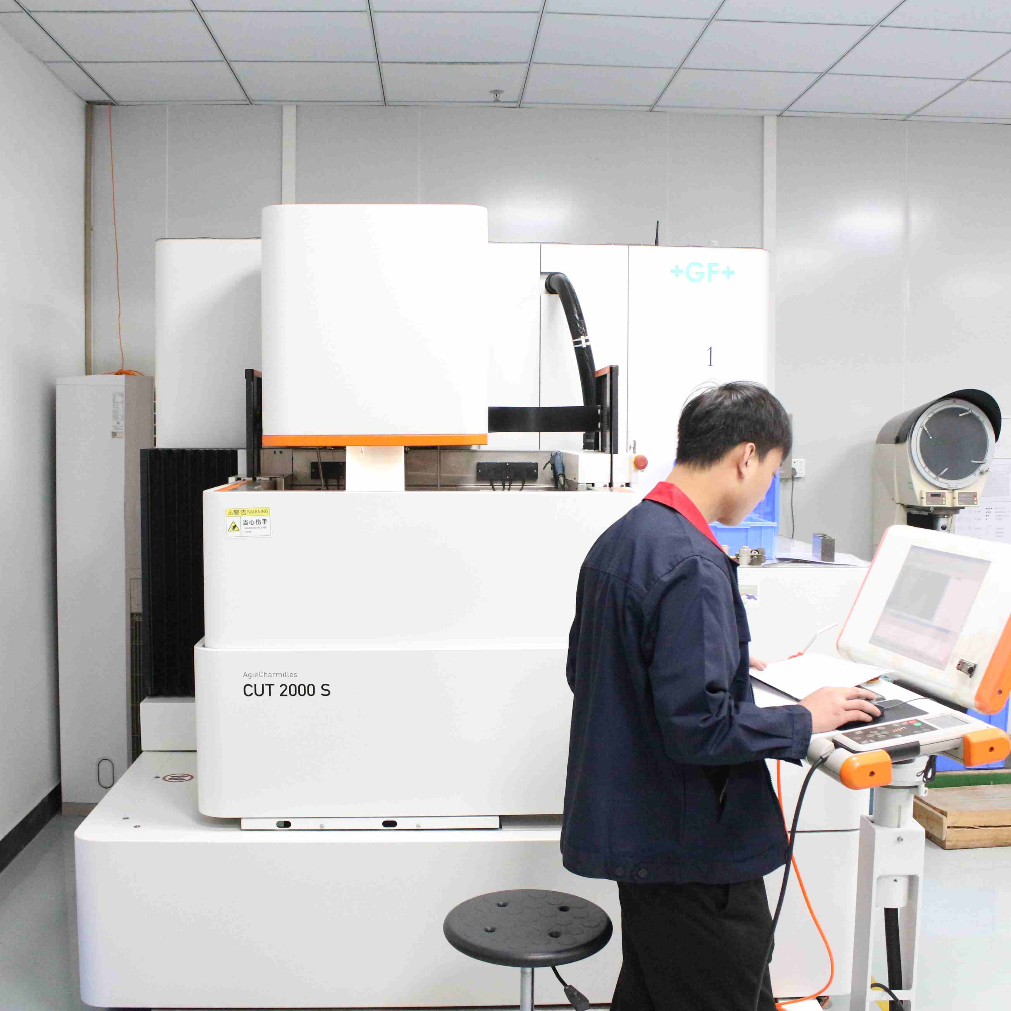
    Meta description: A ±0.002 mm profile deviation on a wire EDM drawing looks like a single number, but it actually demands five tightly controlled links — wire, electricity, water, path, and environment. Here is why this specification is really a systems engineering problem, and what to look for in a precision wire EDM partner.   On any precision mold or stamping die drawing, you will often find a note such as: "Maximum allowable profile deviation: ±0.002 mm." For someone unfamiliar with wire EDM, that line can look like just another tolerance. But for an experienced slow wire EDM (WEDM) operator, those two microns are a wake-up call. They mean that from machine selection and electrical parameters to wire condition, water quality, cutting path, and even workshop temperature, every link in the chain must reserve room for those two microns.   Get any one of those links wrong, and the part will fail inspection. This article breaks down why ±0.002 mm is fundamentally a systems engineering challenge — and what a B2B buyer should expect from a serious precision EDM partner.   What ±0.002 mm Actually Means To put this number in perspective: l 2 microns = 0.002 mm l A human hair is roughly 70 microns in diameter l That means the allowable deviation is less than 1/35 of a hair's thickness No single component of a wire EDM machine, on its own, can hold a 2-micron profile. The number is only achieved when wire, electrical energy, dielectric water, tool path, and ambient conditions are all dialed in together. That is the essence of systems engineering: an end result that emerges from the whole, not from the sum of its parts. The 5 Critical Links in a Precision Wire EDM Process   1. Electrode Wire Selection and Tension Control The "cutting tool" in wire EDM is not a solid end mill — it is a brass or molybdenum electrode wire as thin as 0.10–0.30 mm. That wire already carries its own diameter tolerance. Why it matters: l If a Ø0.25 mm brass wire is actually 0.002 mm oversized, the discharge gap widens and the finished profile shifts outward. l If wire tension fluctuates, the wire vibrates during cutting, and that vibration transfers directly to the workpiece surface as waves or dimensional scatter. What good looks like: l Precision-grade electrode wire with tightly controlled diameter l Continuous wear monitoring with in-process compensation l An automatic tension control system that holds tension fluctuation within a narrow band even at high wire speeds This is one area where entry-level and high-end machines diverge sharply. Closed-loop tension is not optional for ±0.002 mm work.   2. Precise Matching of Discharge Parameters Wire EDM removes material through pulsed electrical discharge. Each pulse carves a tiny crater, and the depth of that crater is set by the energy of the pulse. The core trade-off: Higher discharge energy Lower discharge energy Faster cutting Slower cutting Rougher surface Smoother surface Larger profile deviation Tighter profile deviation   For ±0.002 mm profile accuracy, the finishing pass must run on very low energy: l Narrower pulse width l Lower peak current l Often a dedicated "non-electrolytic power supply" or "ultra-fine finish circuit" for the final skim cut The downside is well known: cutting time can 3–4x compared to a roughing cut. That is one reason micro-precision EDM work is never quoted cheaply — the machine time is real.   3. The Hidden Impact of Water Quality and Filtration This is the most overlooked link in the chain, and one of the most punishing when it is ignored. Wire EDM uses deionized water as the dielectric. The resistivity of that water directly controls the stability of the discharge gap: l Resistivity too low → discharge energy disperses → gap widens → profile runs oversized l Resistivity too high → discharge becomes unstable → wire breakage and abnormal sparking For ±0.002 mm, the typical control band is: l Resistivity held stably above 1 × 10⁵ Ω·cm l Resin tank replacement on a fixed schedule l High-efficiency filtration keeping the machining zone clean The condition of the resin tank and the micron rating of the filter elements show up, line by line, in the final profile accuracy. A shop that treats its water system as an afterthought cannot hold 2 microns.   4. Process Intelligence in Cutting Path and Stock Allocation Two experienced process engineers can be handed the same drawing, program two different paths, and get two very different results. Path planning is where experience shows up in the part. The standard multi-pass strategy for ±0.002 mm: 1. Rough cut — remove the bulk of the stock and release internal stress 2. Semi-finish cut — correct any deformation caused by stress release 3. Finish cut (skim cut) — reach the final size and surface quality Each pass has a precisely calculated offset, derived from: l Material thickness l Geometric complexity l The behavior of the specific machine If the offset is too generous, the finish pass cannot clean up the prior pass's marks. If it is too tight, the final pass may not reach the reference surface at all. The "feel" for these numbers is built from years of trial cuts and accumulated data — not from a parameter sheet.   5. The Influence of Temperature and Environment The last, and most underestimated, variable is the ambient environment. l A 2-micron error is perfectly acceptable in a 20 °C ± 0.5 °C constant-temperature workshop l In an uncontrolled environment, even ±2 °C of fluctuation can consume most of the tolerance through thermal expansion and contraction of the workpiece That is why precision wire EDM workshops invest in: l Constant-temperature air conditioning l Long equalization times before machining l Coolant and air-flow management around the work area A supplier that machines precision parts in a general factory floor — even with a great machine — will struggle to hold 2 microns consistently.   Why This Matters for Your Project If your drawing calls for ±0.002 mm profile deviation, you are not buying a machining service. You are buying access to a controlled system: l A machine with closed-loop wire tension l A generator with micro-finish circuits l A water system with stable resistivity l A process engineer who knows how to plan the path l A workshop that holds temperature steady year-round Any weak link, and the chain breaks. That is why some jobs are simply not something every factory can take, regardless of what their marketing says. Looking for a Precision Wire EDM Partner? At Dongguan HongYu Mould Co., Ltd., ±0.002 mm profile deviation is a daily production target — not a special request. Our capacity is built around: l AgieCharmilles, Sodick, and Waida high-end slow wire EDM platforms l A constant-temperature workshop with controlled humidity l In-house deionized water systems with continuous resistivity monitoring l A multi-pass cutting database refined over 19 years of export work l 19+ years of dedicated experience serving European and Japanese B2B customers in automotive, electronics, IC packaging, and industrial machinery   We work directly with mold makers, stamping die builders, and precision parts manufacturers who need tolerances they can actually rely on — and who need a partner that can explain, in plain language, where every micron of their tolerance is being spent.   Send us your drawing, and we will tell you honestly whether it is buildable, and how. 👉 sales01@dghongyumold.com for a feasibility review within one business day.  
  • Why ±0.005mm Precision Is the New Baseline for Stamping Mold Components in 2026
    Why ±0.005mm Precision Is the New Baseline for Stamping Mold Components in 2026 Aug 27, 2026
    What Changed? Three forces converged to push the precision floor downward: · EV component miniaturization — Battery casings, busbar connectors, and sensor housings demand absolute dimensional stability at high volume. A 5-micron deviation across a progressive die with 12 stations compounds into assembly failures downstream.   · Micro-connectors and semiconductor packaging — IC leadframe molds and 0.4mm-pitch connector tools require features at the 10–20 micron level. The punch and die themselves must be held to half that tolerance or better.   · Assembly automation — European and Japanese buyers are eliminating manual inspection stations. Parts must arrive dimensionally consistent enough to feed directly into automated assembly lines with zero sorting.   What It Takes to Hold ±0.005mm Achieving five-micron tolerance on stamping mold components is not about a single machine — it is about a system. The chain breaks at the weakest link.   · Material — Tungsten carbide for wear-critical punches and dies (HRC 85–90). Powder metallurgy steels for high-strength applications. Material uniformity and purity are non-negotiable; internal inclusions at the micron level cause precision drift over production runs.   · Machining — High-precision surface grinders with ±0.001mm positioning accuracy. Slow-wire EDM for complex geometries, achieving Ra ≤ 0.2μm surface finish. Every step monitored with in-process measurement.   · Heat treatment — Vacuum quenching with deep cryogenic treatment (-196°C) to eliminate residual austenite and reduce post-machining deformation by up to 80%. Without this, a part that measures 0.005mm today may drift to 0.012mm after a month.   · Inspection — CMM (Coordinate Measuring Machine) verification on every critical dimension. Optical profiling for micro-features. Full dimensional report shipped with each batch — not on request, but by default. What This Means for Buyers If you are sourcing stamping mold components in 2026, the right question is no longer "Can you hold ±0.01mm?" — any competent shop can. The question is: "Can you hold ±0.005mm consistently across a 10,000-piece batch, with documented CMM data, and repeat it on the next order?"   That consistency is what separates a precision manufacturer from a machine shop. It requires invested equipment, trained operators, disciplined process control, and a quality system that treats every micrometer as a contractual obligation. Our Approach At HongYu Mould, we have been holding ±0.005mm tolerances on stamping mold punches, dies, and inserts for years — serving automotive, electronics, and IC packaging customers across Europe and Japan. Our facility in Dongguan operates AgieCharmilles wire EDM, Waida grinders, and Sodick equipment, with full CMM inspection on every shipment. With 19 years of export experience, we understand that precision is not a spec on a drawing — it is a promise to
  • Tolerance Control for Stamping Die Parts: 5 Key Points
    Tolerance Control for Stamping Die Parts: 5 Key Points Aug 21, 2026
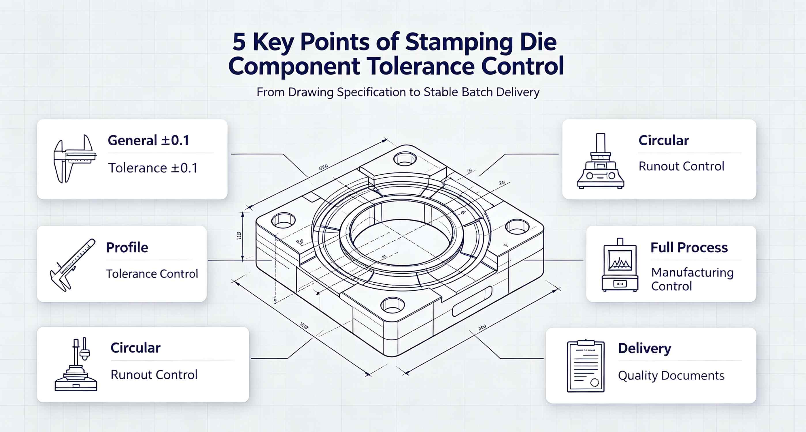
    In the stamping die industry, tolerance control is the core factor determining tool life and product quality. When sourcing die components, buyers from the automotive and home appliance sectors in Europe and North America first evaluate a supplier's understanding and execution of tolerances. This article breaks down 5 key dimensions to help you master tolerance control for stamping die parts. 1. Understanding "General Tolerance ±0.1"   Many drawings specify "General tolerance ±0.1" in the title block or general notes. However, this does not mean all dimensions can be machined to ±0.1. Scope: Applies only to linear and angular dimensions without individual tolerance callouts. Exceptions: Mating surfaces, functional surfaces, and locating dimensions typically have tighter tolerances (e.g., ±0.01 or +0.005). Industry Standards: ISO 2768-m (medium class) corresponds to ±0.1; ISO 2768-f (fine class) corresponds to ±0.05. Tip for Buyers: Always check the general tolerance grade in the title block first, then look for any special tolerance callouts. Combining both gives you the true precision requirement of the part.   2. Geometric Tolerance: Profile of a Surface    Profile of a Surface (symbol ⌒) is one of the most common geometric tolerances in stamping dies. It controls the shape accuracy of curved surfaces or complex contours. Typical Callout: ⌒ 0.01 A (Profile 0.01 mm relative to Datum A) Processing Challenge: High-profile requirements often demand CNC grinding or EDM (Electrical Discharge Machining) rather than simple milling. Inspection Method: CMM (Coordinate Measuring Machine) or profilometer. Key Point: The smaller the profile tolerance, the better the interchangeability of die parts and the more consistent the stamped parts will be. 3. Geometric Tolerance: Circular Runout   Circular Runout (symbol ↙) primarily controls the concentricity of rotating parts such as punches, guide pins, and rollers. Typical Callout: ↙ 0.01 A (Circular Runout 0.01 mm relative to Datum A) Key Influencing Factors: Clamping eccentricity Thermal deformation during grinding Quality of center holes Process Assurance: Using two-center mounting + multiple finish grinding passes can reliably control runout within 0.01 mm. Common Misconception: Circular runout is not the same as coaxiality. Runout is a composite error (including roundness, coaxiality, and axis straightness), making it a stricter requirement.   4. How to Ensure Consistency Through Process Control Tolerance control goes beyond drawing annotations — it must be strictly executed throughout the manufacturing process. ① Material Pre-treatment Steel should undergo stress-relief annealing before rough machining to eliminate internal stresses and reduce subsequent deformation. For high-precision parts (punches, insert cavities), vacuum heat treatment is recommended to control distortion within 0.02 mm. ② In-Process Inspection Perform first-article inspection on critical dimensions after each operation. Adjust parameters immediately if deviations are found. For batch production, use SPC (Statistical Process Control) to monitor dimensional trends and detect drift early. ③ Environmental Control Precision grinding workshops should maintain a constant temperature of 20±2°C to avoid thermal expansion errors. Before measurement, allow parts to stabilize in the temperature-controlled room for at least 2 hours. 5. Quality Documentation for Delivery   European and American customers typically require the following documents upon delivery: Inspection Certificate: Lists actual measured values for all critical dimensions, compared against drawing tolerances. Geometric Tolerance Report: Actual data for profile, runout, and other GD&T requirements. Material Certificate: Chemical composition and heat treatment records for the steel used. One-Sentence Summary: Tolerance control is not about "whether you can do it once," but "whether you can reproduce it consistently." Suppliers with robust process control and inspection systems are the ones worth long-term partnerships. Summary Table Key Point Core Content Buyer Priority General Tolerance ±0.1 Understand scope; distinguish from special tolerances ⭐⭐⭐ Profile Control Surface accuracy; impacts stamped part consistency ⭐⭐⭐⭐ Runout Control Concentricity of rotating parts; affects die life ⭐⭐⭐⭐ Process Consistency Full-cycle control: material, inspection, environment ⭐⭐⭐⭐⭐ Delivery Documents Inspection reports, material certificates ⭐⭐⭐   Looking for a reliable stamping die parts supplier? Contact us today. We offer one-stop service from drawing interpretation and process design to final inspection — ensuring every part meets your tolerance requirements.
  • The Hidden Knowledge Crisis in Precision Mold Manufacturing
    The Hidden Knowledge Crisis in Precision Mold Manufacturing Aug 07, 2026
    A Real Technical Gap On Production Site A Japanese-invested mold factory based in Dongguan employed Mr. Tanaka, a senior Japanese technician with 22 years of working experience. His core expertise was precision punch inner-hole EDM processing, which required ultra-strict taper tolerance controlled within 0.005 mm.   After Mr. Tanaka retired and returned to Japan, three technicians took over his workstation one after another, yet none could deliver qualified products:   l The first operator: Taper reached 0.012 mm, all workpieces scrapped; l The second operator: Carbon residue covered the hole wall, rejected by clients; l The third operator: Only achieved 0.008 mm taper, with a 3-day delivery delay. The factory had no choice but to outsource the entire batch to a precision mold factory in Hong Kong at three times the original price.   This case is far from unique. Over the past five years, nearly all Japanese-funded mold factories in the Pearl River Delta and Yangtze River Delta have faced identical troubles. Once senior Japanese craftsmen leave, the yield and efficiency of their stations drop drastically, and the technical gap cannot be filled quickly.   The Unique Tacit Skills Possessed by Mold Masters Most people simply define the masters’ competitiveness as vague "craftsmanship" or "intuition". Taking EDM processing as an example, their exclusive practical capabilities can be divided into three clear parts:   Predictive Compensation for Electrode Wear Ordinary technicians follow a repetitive workflow: trial cut → measure → adjust parameters repeatedly. Veteran masters adopt a forward-thinking method: l Evaluate drawings, workpiece material, depth-diameter ratio and tolerance requirements at first sight; l Calculate electrode wear rate in advance; l Pre-set tapered compensation structure (thicker top, thinner bottom) during programming. Others need three rounds of cutting to reach standards, while masters finish processing in one pass with more stable taper accuracy.   Auditory Judgment of Chip Evacuation This capability relies on long-term on-site practice instead of blind guesswork. Senior EDM technicians judge internal machining status merely by the discharge sound of equipment: l Crisp crackle: Smooth chip evacuation; l Dull puff sound: Chips pile up, electrode lifting required; l Sudden silence: Short circuit happens, reduce servo speed instantly. This perceptual experience cannot be compiled into formal SOPs and can only be gained through years of machine operation.   Material Memory for Tungsten Carbide Machining Different tungsten carbide brands, cobalt content and sintering processes lead to completely different EDM performance. Senior technicians who stay in one factory for over a decade form unique material muscle memory. Faced with new tungsten carbide grades, they adjust current parameters immediately by distinguishing spark color and discharge sound.   In contrast, young technicians frequently switch processing materials between SKD11, tungsten carbide and powder high-speed steel. They never get enough time to master the processing characteristics of a single material thoroughly. Three Root Causes for Failed Skill Inheritance Young generations are not unwilling to work hard; the core problems lie in the flawed industrial operation system.   Collapsed Systematic Training Mechanism The standard growth path of Japanese mold technicians is long and complete: 3-year apprentice → 5-year assistant → 10-year independent operator → professional craftsman. The system includes standardized apprenticeship, regular skill assessment and rotational training.   However, domestic mold factories face tight order deadlines. New apprentices are required to operate machines independently after only 3 months of learning, with no time for slow, systematic skill training.   Tacit Experience Cannot Be Digitized Most of the masters’ core experience is unquantifiable tacit knowledge: l Slow down servo speed by 15% for certain holes; l Increase flushing pressure by 0.2 MPa for specific materials; l Severe electrode wear appears on the third arc section of special electrode shapes. These real-time adjustment rules cannot be written into CNC codes or teaching videos. Once the senior technician leaves, the valuable experience disappears completely.   Declining Industry Attractiveness for Young People Young job seekers have more career options nowadays. Food delivery, live streaming and e-commerce provide cleaner working environments with similar entry salaries. Most young workers regard mold workshops as a temporary job, and few intend to devote 20 years to precision machining. Feasible Solutions to Solve the Skill Gap Crisis There is no perfect one-step solution, yet three practical directions can help factories retain and pass down veteran experience:   Build a Complete Machining Experience Database Record full dimensional data of every mold batch, including EDM parameters, material batches, electrode wear rate and final taper measurement results. Establish a searchable "material-parameter-processing result" comparison table for new operators to reference and reduce blind trial and error.   Combine Standardized Operation with Adjustable Flexibility Avoid locking all processing parameters rigidly. Set unified baseline parameters with clear adjustable ranges, and mark corresponding adjustment logic under different machining conditions. This balances standardization and flexible on-site judgment.   Train Multi-skilled Compound Technicians Break single-station fixed work mode. Encourage EDM operators to learn wire cutting, surface grinding and mold assembly. Workers with comprehensive cross-process knowledge can solve complex machining problems better and are less replaceable.   Japanese mold masters’ irreplaceable capacity is not some mysterious super skill. The real crisis is that decades of accumulated experience has never been recorded, standardized or passed down systematically.   This technical succession dilemma troubles the whole precision manufacturing industry, not individual factories. If enterprises ignore experience inheritance at present, we will face the same huge gap when our current senior workers retire.   The core question every mold manufacturer must answer: Who will take over our accumulated craftsmanship in the future?  
  • Sustainability in Stamping Die Production: Lower Scrap & Extend Die Service Life
    Sustainability in Stamping Die Production: Lower Scrap & Extend Die Service Life Jul 30, 2026
    Metal stamping die manufacturing has long prioritized speed and precision. Today, sustainability has become a key competitive factor for global tooling suppliers. For stamping die factories, sustainable manufacturing is eco-friendly and cost-effective, focusing on reducing production scrap, cutting rework, and extending die service life.   High scrap rates and short die lifespans are the main causes of resource waste, high operational costs and extra carbon emissions in stamping production. Optimizing die design, materials and processing workflows can help manufacturers achieve low-waste production and long-term cost savings. Why Traditional Stamping Die Production Is Unsustainable Traditional stamping die production suffers from severe resource waste, mainly caused by outdated design and processing methods:   High scrap output: Unreasonable die clearance, poor surface finish and unstable heat treatment cause burrs, deformation and dimensional errors, leading to massive defective products and scrap.   Premature die damage: Low-grade materials, unoptimized structures and lack of maintenance result in rapid wear, chipping and cracking of punches and die inserts.   Frequent die replacement: Short die service life requires repeated tool production, consuming extra steel and machining energy and generating industrial waste.   Low energy efficiency: Unstable die performance causes frequent production downtime and debugging, increasing indirect energy consumption.   Simply put, short die life and high scrap rates equal high costs and high carbon emissions. Sustainable die manufacturing solves these fundamental pain points efficiently.   Lower Scrap Rates via Precision Die Optimization Most stamping scrap stems from flawed die design and imprecise machining rather than raw material issues. Optimizing tooling structure and processing is the most efficient way to reduce waste.   DFM Optimization for Stamping Die Structure Pre-production DFM optimization fixes potential structural defects. Optimizing blanking clearance, springback compensation and progressive die layouts minimizes burrs and deformation, stabilizing product yield and greatly reducing rework scrap.   Ultra-Precision Machining & Surface Treatment Precision wire EDM and CNC grinding guarantee consistent die tolerance. Fine polishing up to Ra ≤ 0.2μm avoids metal adhesion and surface defects. Stable tool precision eliminates batch scrap in mass stamping production.   Modular Die Insert Design Modular insert design replaces only worn punches and cavities instead of the whole die set. It retains intact die bases, drastically cutting steel consumption and reducing overall tooling waste. Extend Die Service Life with Scientific Material & Process Upgrades Extending die service life reduces frequent tool replacement and machining waste, serving as the core of sustainable stamping production. Scientific upgrades can boost die lifespan by 30%–100%.   Rational High-Performance Material Selection Scenario-based material selection prevents premature die failure. Tungsten carbide suits high-volume precision stamping, while high-performance steel including SKD11, M340 and ASP23 powder steel delivers excellent durability for high-frequency stamping tasks.   Professional Heat Treatment & Surface Coating Precision vacuum heat treatment enhances material toughness and uniformity to avoid deformation and cracking. Professional surface coatings such as TiN, TiCN and DLC form a protective film, reducing friction, wear and oxidation. These treatments effectively extend die service life, lower long-term production costs and reduce resource waste. Sustainability in stamping die production is not just an environmental slogan, but a practical solution to cut costs and improve efficiency. By optimizing die design, adopting high-performance materials and precision processing, manufacturers can significantly reduce scrap rates and extend tool lifespan. Balancing eco-friendly production and product reliability helps tooling suppliers stand out in the competitive global market.
  • Tungsten Carbide WEDM Finishing Allowance Explained
    Tungsten Carbide WEDM Finishing Allowance Explained Jul 27, 2026
    Having worked with tungsten carbide punches for many years, I'm often asked this question: What is the optimal amount of allowance to leave during the final pass of slow wire drawing precision machining?   To be honest, I used to rely solely on intuition—assuming that any tool would work. That changed when a group of customers reported inconsistent durability: some blades could withstand up to 300,000 uses, while others broke after just 100,000. Upon inspection, the issue turned out to lie in the allowance left during the final blade repair.   Since then, we have tested all five thickness levels—0.01 mm, 0.015 mm, 0.02 mm, 0.025 mm, and 0.03 mm—and today we'll present the results in detail.   Why is the residual allowance during the final blade sharpening process so critical? Slow wire-cutting of tungsten carbide operates on the principle of layer-by-layer removal by electrical discharge. During rough cutting, high energy is applied for rapid processing, but this leaves a "white layer" on the surface—representing re-solidified microstructure. This layer is hard yet brittle and contains microcracks; failure to remove it completely may serve as the initiation point for cracks during stamping.   The final grinding operation aims to completely remove this white layer while achieving a smooth surface with minimal stress.   If the remaining space is too large and the final cut is too deep, new white layers will form, and dimensions may easily deviate from specifications.   The remaining margin is too narrow; the white layer beneath the first cut isn't fully removed, which amounts to ineffective whitening. So, this number must be exactly right.   Our Actual Measurement Data   condition of experiment : Material: KG7 tungsten carbide, thickness 8 mm Wire diameter: 0.25 mm brass wire Rough cutting parameters: Current 12 A, Pulse width 8 μs Cutting parameters: Decrease progressively; reduce the voltage to 40% of the coarse-cutting level on the final pass   Final clearance surface roughness (Ra) White layer thickness dimensional stability overall merit 0.01mm 0.6μm Approximately 2–3 μm in size, with occasional residual particles preferably passing, but unstable 0.015mm 0.5μm Approximately 1–2 μm in size, essentially clean good recommend 0.02mm 0.45μm <1 μm, clean good optimal 0.025mm 0.4μm clean There are slight fluctuations. Available, but size control is more challenging 0.03mm 0.35μm clean The fluctuation is pronounced. Not recommended due to significant size risks     Conclusion: 0.02 mm is the optimal solution. Our tests demonstrate that KG7 tungsten carbide with an 8 mm thickness achieves optimal overall performance when the final tool-sharpening allowance is maintained at 0.02 mm.   Why this number? First, a thickness of 0.02 mm is sufficient to completely penetrate the white layer left by the previous cut. After cutting, the sample was subjected to microhardness testing, and no significant softening layer was observed on the surface.   Second, a cutting depth of 0.02 mm is not significant for tungsten carbide and does not create additional heat-affected zones due to excessive single-discharge energy. The surface roughness can be achieved at approximately Ra 0.45 μm, which is sufficient for the punch application.   Third, it exhibits excellent dimensional stability. Even with a slightly larger allowance (0.03 mm), although the surface becomes smoother, excessive cutting depth may cause fluctuations in wire deflection, leading to reduced dimensional consistency. Given the required tolerance of ±0.002 mm, this risk is not worthwhile.   How to adjust for different thicknesses? Of course, 0.02 mm isn't a universal solution. We've also tested tungsten carbides with varying thicknesses: · For thickness ≤5 mm: the allowance can be set at 0.015 mm, as thin plates dissipate heat rapidly and their white layer is inherently thin.   · For thicknesses of 10–15 mm: It is recommended to reduce the allowance to 0.025 mm, as thicker plates develop a deeper white layer during rough cutting and require an additional margin for complete penetration.   · Thickness>15 mm: We generally do not recommend cutting through the entire thickness in a single pass with slow-speed wire cutting, as this may lead to cracking. Instead, we recommend first performing a wire-cutting operation to create a preliminary groove, leaving a 0.5 mm gap for subsequent grinding on the milling machine. The amount of material left after the final sharpening pass when performing slow wire-cutting on tungsten carbide is not a fixed value; it depends on the material grade, thickness, and rough-cutting parameters.   However, if you are new to this process or lack confidence, starting with a diameter of 0.02 mm is highly unlikely to result in errors. Currently, 90% of our tungsten carbide punches meet this specification, and customer feedback indicates stable service life with a significant reduction in chipping rates.   That's how you make molds—there's no magic formula; it simply comes down to paying close attention to every digit after the decimal point.   If you're also making tungsten carbide punches, feel free to reach out for a discussion. There's no need to place an order—just exchanging insights about the manufacturing process would be great.  
  • High-Efficiency & Low-Deformation Machining Technology for Powder High-Speed Steel and Tungsten Carbide
    High-Efficiency & Low-Deformation Machining Technology for Powder High-Speed Steel and Tungsten Carbide Jul 17, 2026
    In precision mold manufacturing,powder metallurgy high-speed steel (PM HSS) and tungsten carbide (WC) are critical high-performance materials. Their high hardness, excellent wear resistance and stable microstructure make them ideal for new energy, medical, 5G and long-life stamping mold components.   Yet their high hardness and dense structure create tough machining challenges. Traditional processing leads to severe tool wear, thermal deformation and dimensional errors, failing micron-level precision requirements. Thus, high-efficiency, low-deformation machining processes for PM HSS and WC have become key industry competitiveness.   Material Advantages & Machining Pain Points   Powder Metallurgy High-Speed Steel (PM HSS) PM HSS adopts powder metallurgy sintering, free of carbide segregation and internal defects. Its uniform structure and balanced mechanical properties reduce heat-treatment deformation by 30%–50% vs conventional HSS, perfect for ultra-precision inserts, durable pins and complex mold components.   Key Pain Points: High alloy content increases cutting resistance; improper parameters induce residual stress and size deviation; mismatched tools greatly reduce machining efficiency.   Tungsten Carbide (WC) Tungsten carbide features exceptional hardness, strength and wear resistance. It is widely used in micro-precision mold cores and fine stamping parts, maintaining stable precision under high-frequency friction and impact.   Key Pain Points: High brittleness easily causes chipping and micro-cracks; concentrated cutting heat triggers thermal deformation, while traditional machining is inefficient with poor surface finish requiring extra polishing.   Core Low-Deformation & High-Efficiency Machining Processes   Constant-Temperature Precision Machining System Thermal deformation is the main cause of dimensional failure for hard-material parts. Leading manufacturers apply 20±1℃ constant-temperature workshops and machine tool thermal calibration to eliminate temperature interference.   Combined with MQL minimum quantity lubrication and low-temperature cooling, this system cuts heat accumulation and thermal stress, controlling workpiece deformation within ±0.002mm for reliable micron-level precision.   Optimized Tool Matching & Cutting Parameters Professional tool matching ensures balanced precision and efficiency. PM HSS finishing uses heat-resistant ultra-fine carbide cutters with high-speed low-feed strategies to lower cutting resistance and residual stress. Tungsten carbide adopts diamond grinding and specialized EDM to solve poor machinability and fast tool wear.   We have standardized parameters for ASP60, KG7 and other mainstream grades. Layered cutting disperses stress to prevent deformation, boosting machining efficiency by 30%–50%.   One-Clamp Five-Axis Composite Machining Traditional 3-axis repeated clamping causes positioning errors and stress deformation. The five-axis one-clamp machining process completes complex curved, special-shaped and multi-angle structures in a single setup.   This method eliminates secondary clamping deformation, improves batch consistency, and shortens hard-part cycle time by over 40%, becoming the preferred high-end mold processing solution. Stress Relief & Precision Post-Processing Residual stress leads to long-term dimensional instability. We perform secondary stress relief after roughing to avoid post-production deformation. Tungsten carbide parts receive precision grinding and ultra-mirror finishing to remove micro-defects, optimize surface quality and extend mold life.   Practical Application Value & Industry Benefits Our optimized process resolves hard-material machining defects including low precision, deformation and low efficiency, delivering three core advantages for high-end new energy and medical mold manufacturing:   Ultra-high precision stability: Micron-level tolerance control and 100% pass rate satisfy global clients’ zero-defect standards.   Cost & efficiency improvement: Standardized processing reduces tool loss, rework and lead time, cutting overall production costs.   Extended mold service life: Low-stress machining avoids internal flaws. Combined with PVD/CVD coating, molds achieve greatly enhanced wear and fatigue resistance with doubled lifespan.     As manufacturing precision standards rise, high stability and durability have become essential for mold parts. PM HSS and tungsten carbide will continue dominating high-end precision manufacturing.   Optimized low-deformation processes, standardized parameters and smart equipment help manufacturers break hard-material bottlenecks and gain high-end market competitiveness.   Looking for reliable PM HSS & tungsten carbide precision machining? We offer one-stop DFM optimization, precision machining, stress relief and surface treatment for custom high-quality mold parts worldwide.
  • How to Cut Tungsten Carbide Punches Without Cracking
    How to Cut Tungsten Carbide Punches Without Cracking Jun 26, 2026
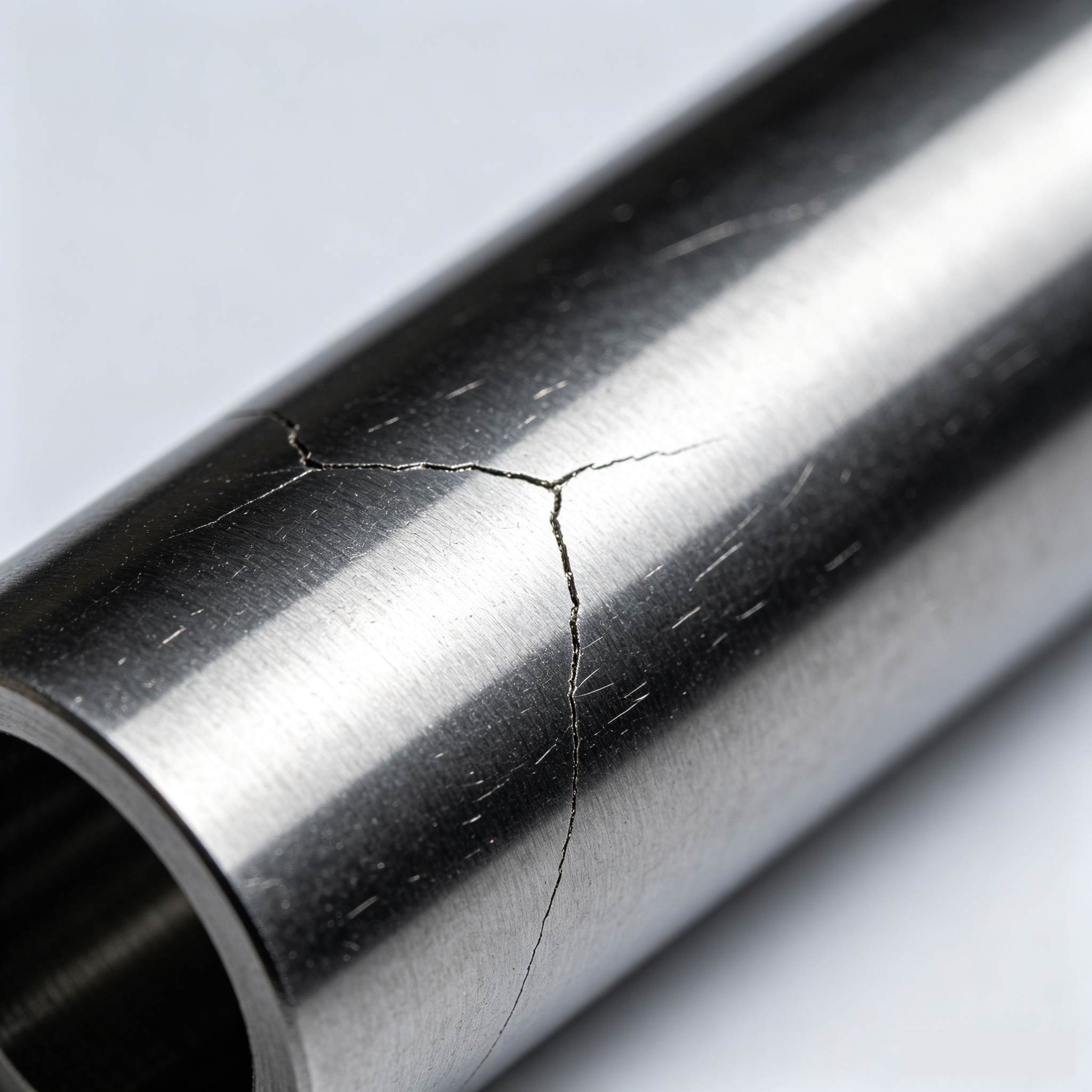
    Why is Tungsten Carbide Prone to Cracking?       Tungsten carbide (hard alloy) is produced by sintering tungsten carbide powder with cobalt binder. Its hardness can reach HRA 89-93, but its elongation is extremely low—in simple terms, it’s “hard but brittle.”     Wire EDM and conventional EDM work by eroding metal with extremely high-temperature electrical sparks. The localized, instantaneous temperatures can reach thousands of degrees, then rapidly cool in the dielectric fluid—this heating and cooling cycle generates thermal stress. If parameters are off, micro-cracks develop on the surface. When the punch is later used in stamping, these cracks propagate under force, causing chipping or complete breakage. Therefore, the key issue with cutting tungsten carbide isn’t whether it can be cut, but how to control heat input and cooling rates.      Wire EDM: Getting the Parameters Right is Paramount     We primarily use wire EDM for manufacturing tungsten carbide punches. The following parameters are non-negotiable:   Don’t Use Excessive Current     Many operators assume higher current means faster cutting. For tungsten carbide, higher current deepens the heat-affected zone and thickens the “white layer” (recast layer). This layer is a breeding ground for cracks.     Our approach: Use moderate current for rough cutting. For finishing, drop the current to a third (or lower) of the roughing value. It is better to make an additional pass than to cut fast and risk thermal cracking.   Keep Pulse Width Short     Longer pulse widths mean higher energy per pulse and faster erosion, but also more damage. We typically control pulse widths between 2–6 microseconds and use sub-2-microseconds for finishing.   Monitor Dielectric Resistivity     If the deionized water’s resistivity is too low, arcing can occur, damaging the work surface. We keep resistivity at 10–15 kΩ·cm; this is checked every shift and the resin is replaced as needed.   Maintain Stable Wire Speed     Too fast and the wire may snap; too slow and chip evacuation suffers. We set speeds between 4–6 m/min, based on wire size and part thickness, ensuring effective flushing without vibration.   Use Multiple Passes as Standard     We always run at least three passes on tungsten carbide punches: rough → finish 1 → finish 2. Cutting energy is reduced with each pass; the final pass is like a gentle “sweep,” producing a near-invisible white layer and an Ra better than 0.8μm.     EDM Drilling: Small Holes are the Most Challenging     Punches may need oil holes or vent holes as small as 0.3 mm—a job for EDM drilling.   The biggest challenge here is chip removal. If debris isn’t flushed, it causes repeated discharge on the hole wall, leading to surface burns or, in severe cases, outright cracking.   Our best practices:   Use straight copper tube electrodes—bent tubes will wander and burn the hole wall. Ensure sufficient flushing pressure so debris is pushed out effectively. Don’t feed too quickly; at the first sign of short-circuiting, retract immediately—never force the electrode.   Post-EDM: What Comes Next?     Cutting is not the end. Two steps are critical after machining:   Inspect the White Layer     We use a magnifier or metallographic microscope to check the edge; if the white layer is visible, we gently polish it off with fine sandpaper. Leaving the recast layer is a hidden trouble for future chipping.   Stress Relieving (Low-Temperature Tempering)     Tungsten carbide punches may retain residual stresses after cutting. If possible, we perform a low-temperature tempering (180–220°C) to effectively release internal stress and stabilize dimensions.     Summary     To “cut” tungsten carbide punches without cracking, it really comes down to three points: Don’t use excessive current; use more finish passes. Ensure effective cooling (flushing) and chip removal. Don’t use the punch straight after machining—inspect the white layer and relieve stress.   This is how we do it at our workshop. Clients call our punches durable and resilient—not because of any “secret trick,” but because we carefully control every process detail.   If you’re struggling with the yield of tungsten carbide punches, let’s discuss—no need for business, sometimes exchanging experience is priceless.
  • When to Replace or Regrind Stamping Tooling: A Practical Guide for Die Maintenance
    When to Replace or Regrind Stamping Tooling: A Practical Guide for Die Maintenance Jun 17, 2026
    In the world of metal stamping, tooling wear is inevitable. But knowing exactly when to replace a punch or regrind a cutting edge can mean the difference between high-quality output and costly downtime.   When to Replace a Punch Punches are among the most stressed components in a stamping die. Here are the critical signs that it's time for replacement:   Visible Wear or Chipping Inspect the punch tip regularly. If you notice: Rounded or dull cutting edges Small chips or cracks on the surface Uneven wear patterns Replace immediately. Continuing to use a chipped punch can damage the die button and produce burrs on your parts.   Excessive Burr Height Burr height is one of the most reliable indicators. Measure burrs periodically: Acceptable: Less than 10% of material thickness Warning: 10–15% — plan for replacement soon Critical: Over 15% — replace immediately   Dimensional Drift If stamped parts begin to fall outside tolerance, even after adjusting the press parameters, the punch may be worn beyond its useful life.   Increased Punching Force A sudden or gradual increase in press tonnage often indicates that the punch is dull and requires more force to shear through the material.   Surface Finish Degradation When the sheared edge becomes rough, torn, or shows excessive rollover, it's time to evaluate punch condition. General Rule of Thumb For standard tool steels punching mild steel (up to 3mm thick), expect a typical punch life of: 50,000 – 200,000 strokes​ before resharpening Replacement after 3–5 regrinds, or when the punch length is reduced by 20%   When to Regrind Cutting Edges Regrinding restores sharpness without replacing the entire tool. Proper timing maximizes tool life while maintaining quality.   Key Indicators for Regrinding   1. Burr Threshold Exceeded As mentioned above, once burr height reaches 10–15% of material thickness, schedule a regrind. Do not wait until it hits the critical zone.   2. Edge Radius Increase Use an optical comparator or microscope. If the cutting edge radius exceeds 0.05–0.10 mm, regrinding is overdue.   3. Galling or Pick-Up When material starts sticking to the punch or die surface, it indicates micro-welding due to heat and friction. Regrinding removes the damaged surface layer.   4. Sound and Vibration Changes Experienced operators often hear when a die is dull. A change from a clean "snap" to a dull "thud" or increased vibration signals the need for maintenance.   5. Consistent Production Counts Many shops adopt a preventive approach: Regrind every 50,000 – 100,000 strokes​ depending on material type and thickness Track actual performance and adjust intervals accordingly   Recommended Regrind Amount Remove only 0.05 – 0.15 mm​ per regrind Avoid removing too much material at once, as this generates heat and can soften the tool steel Best Practices for Maximizing Tool Life Practice Benefit Use proper lubrication Reduces friction and heat buildup Maintain correct clearance Prevents excessive wear and chipping Align punches precisely Eliminates uneven loading Store tools properly Prevents corrosion and accidental damage Keep detailed maintenance logs Enables data-driven replacement decisions   The decision to replace a punch or regrind a cutting edge should never be based on guesswork. By monitoring burr height, dimensional accuracy, edge condition, and production counts, you can implement a predictive maintenance strategy that reduces unplanned downtime and extends tool life.A well-maintained die is a profitable die.    
  • Impact of Surface Treatments—Nitriding, Titanium Coating, and Sandblasting—on Stamping Die Life
    Impact of Surface Treatments—Nitriding, Titanium Coating, and Sandblasting—on Stamping Die Life Jun 12, 2026
    In daily production of metal stamping dies, issues such as die wear, galling, chipping, and rusting are key factors affecting production efficiency. As the hardness and wear resistance of die base materials are limited, surface treatment processes are the most efficient and commonly used methods to increase the number of stamping operations and extend die life. Among them, nitriding, titanium coating, and sandblasting are the most widely applied techniques. The principles, characteristics, and effects of these three methods on stamping die life differ significantly, and each is suited to specific production scenarios.   Nitriding is the most fundamental and cost-effective long-term surface treatment in the die industry, and is the preferred choice for standard stamping dies. Through high-temperature diffusion, a dense nitrided hardening layer is formed on the die surface. This process does not change the overall dimensions of the die and does not affect assembly accuracy. Nitriding can significantly enhance surface hardness, improving wear resistance, galling resistance, and minor corrosion resistance, effectively preventing sheet galling and moderate wear during stamping. Dies treated with nitriding can achieve two to three times longer service life, making this method suitable for stainless steel, general cold-rolled steel, and other conventional stamping applications. However, its limitations are also apparent: the hardening layer is relatively thin, and impact and high-temperature resistance are moderate, making it unsuitable for high-speed stamping or stamping of high-hardness materials.   Titanium coating is a high-end reinforcement process and is the most effective method for significantly increasing die life. Titanium coating involves depositing an ultra-thin layer of high-hardness, highly lubricious titanium alloy on the die surface. The coating far exceeds the nitrided layer in hardness and offers exceptional wear resistance, high-temperature resistance, and a low coefficient of friction. During stamping, the coating can greatly reduce friction between the die and the sheet, completely eliminating galling, carbon buildup, and sticking issues. Even under high-speed, high-frequency operations, the die surface remains smooth. A high-quality titanium-coated die can last five to ten times longer, making it ideal for high-speed continuous stamping, stainless steel, and high-strength steel in heavy-duty applications. The only downside is the higher cost and the fact that the coating cannot be locally repaired once damaged.   Unlike the previous two reinforcement methods, sandblasting is a physical surface treatment whose main function is not to enhance hardness, but to optimize surface condition. Sandblasting uses high-pressure abrasive particles to impact the die surface, refining the surface texture, removing oxide scale and machining marks, and eliminating stress concentrations. This process improves demolding performance, reduces burrs on stamped products, and slightly mitigates galling issues. However, it does not increase die hardness or wear resistance, offering only a minimal improvement to die life. Sandblasting is mainly used for pre-treatment, improving appearance, and relieving surface stresses.   In summary, each of these three methods has its own advantages and is fit for particular applications. For low-cost, standard mass production applications, nitriding is the preferred choice. For high-speed, high-hardness sheet metal and long-life production, titanium coating is recommended. For pre-treatment and surface finish optimization, sandblasting should be selected. Effectively combining these surface treatment techniques can significantly extend die life, reduce maintenance frequency, lower production costs, and ensure stable stamping operations. Such refined die maintenance and appropriate cost control are the keys to increasing efficiency and reducing expenses in stamping production.
  • Three Core Priorities for Stamping Mold Business Owners in 2026
    Three Core Priorities for Stamping Mold Business Owners in 2026 Jun 06, 2026
    The stamping mold industry has moved past the era of relying on high output and low prices to win orders. In 2026, market homogeneity, rising raw material and labor costs, and increasingly strict customer inspection standards have reshaped the industry competition. It now focuses on stable quality, controllable profits and precise customer resources.   There is no need to chase impractical high-tech concepts or blindly expand production capacity. Focusing on these three practical tasks will help mold manufacturers stabilize their business and stand out from competitors. Prioritize Stable Quality, Abandon Unreliable Mass Production Whether for domestic key clients or foreign trade orders, customers value most is mold stability, fewer after-sales problems and worry-free mass production. Many mold factories have sufficient inquiries, yet lose profits and reputation due to repeated mold modifications, burrs, springback, deformation and inconsistent mold service life during production.   In 2026, quality competition is essentially standardized operation competition. We conduct thorough DFM review, precise layout and structural optimization in advance to avoid cracking, scratching and dimensional errors from the source. During production, we strictly control steel selection, heat treatment accuracy and edge polishing processes. Standardized mold testing is implemented to ensure consistent sample quality.   With solid craftsmanship and standardized workflows instead of fancy intelligent equipment, factories can greatly reduce defective rates, stabilize mold precision and service life — the core to retaining old customers and gaining new referrals.   Adopt Refined Cost Control, Avoid Extensive Profit Loss Industry profits have become highly transparent, and raising prices is no longer a feasible solution. Refined cost control equals profit growth. Many mold factories maintain a steady order volume but gain slim profits, mainly due to extensive cost management.   Successful mold owners focus on detailed cost control in every production link. Adopt standardized and modular mold bases to reduce redundant processing and material waste. Optimize processes upfront to cut repeated mold testing and modification costs. Standardize daily mold maintenance and regular replacement of vulnerable parts to extend mold service life and lower rework expenses.   We match materials and processes reasonably, avoiding excessive cost from over-specified materials and quality loss from cutting corners. Precise cost control is the key to securing profits amid fierce low-price competition. Upgrade Service & Select High-quality Tracks, Stop Blind Low-price Bidding The industry shows obvious polarization in 2026. Low-end orders only bring cutthroat price competition, while emerging tracks including new energy, precision electronics and foreign trade offer stable orders and better profits. Mold owners need to actively target high-value markets such as precision stamping, new energy structural parts and export-standard molds to avoid homogeneous low-end competition.   Meanwhile, enterprises must transform from simple mold suppliers to one-stop solution providers. We offer full-cycle services, including pre-production drawing evaluation and process optimization, mid-production manufacturing and trial testing, and post-production mass production support and after-sales maintenance. For foreign trade orders, we comply with international inspection standards and ensure traceable quality and complete compliance documents to expand overseas markets and get rid of price wars. There are no sudden windfalls in the 2026 stamping mold industry, only steady and down-to-earth development. Stabilize quality to lay a solid foundation, control costs to retain profits, and upgrade services to expand market share. By sticking to these three practical priorities, mold enterprises can survive industry reshuffling and achieve long-term stable growth.  
  • Top 5 Trends Reshaping the Hardware Stamping Die Industry in 2026
    Top 5 Trends Reshaping the Hardware Stamping Die Industry in 2026 May 22, 2026
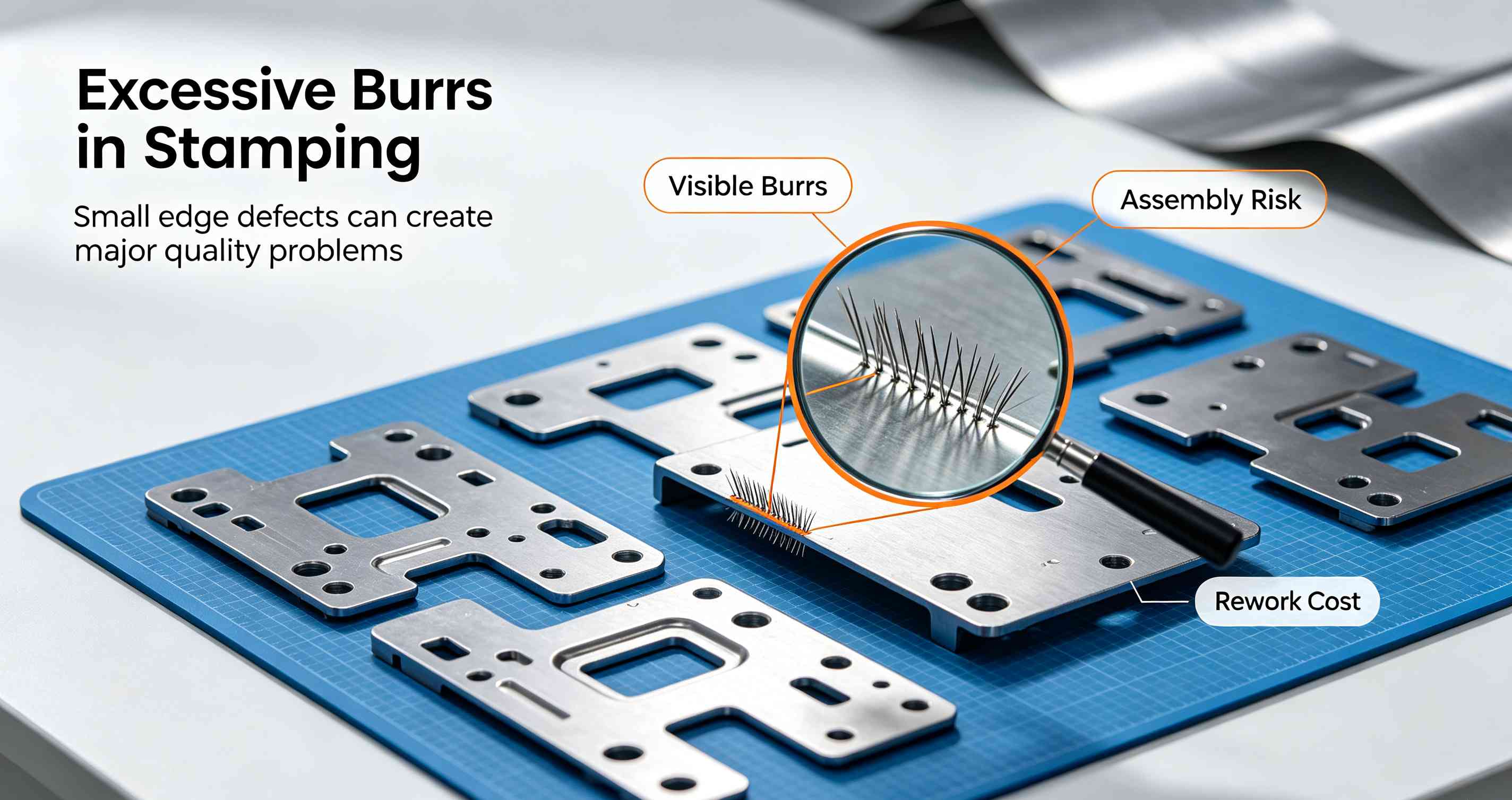
    The hardware stamping die and mold parts processing industry is undergoing its most significant transformation in decades. As we move deeper into 2026, the convergence of downstream demands—from electric vehicles (EVs) and 5G communications to advanced consumer electronics—is forcing a rapid evolution from "traditional metal bashing" to "intelligent precision manufacturing."   For manufacturers, engineers, and procurement specialists, understanding these five core trends is no longer optional; it's essential for survival and growth. 1. Micron-Level Precision Becomes the New Baseline The era of "close enough" is over. While ±0.01mm was once the gold standard for high-end tooling, 2026 has seen ±0.005mm (5 microns)​ become the de facto requirement for securing contracts in automotive and electronics sectors.   The Driver:​ Components for EV battery casings, micro-connectors, and optical modules demand absolute dimensional stability. This shift is pushing manufacturers to invest in high-end CNC grinders, slow-wire EDM, and advanced CMM inspection systems.   The Implication:​ Workshops relying on outdated equipment are finding themselves disqualified from premium RFQs. Precision is now a binary gatekeeper for market entry.   2. The "Burr-Free" Imperative "Zero secondary finishing" is the new battle cry on the factory floor. Downstream assemblers are aggressively eliminating manual deburring stations to cut labor costs and prevent part damage.   The Technology:​ Achieving burr-free stamping hinges on extreme control over punch/die clearance (maintained through rigorous grinding databases), superior edge preparation (mirror-finish cutting edges), and the adoption of high-performance materials like powder metallurgy steels.   The Value:​ Suppliers who can guarantee burr-free parts directly reduce their clients' total cost of ownership (TCO), making them indispensable partners in lean manufacturing ecosystems. 3. Smart Manufacturing Gets Real: AI & Digital Twins Industry 4.0 is moving from the showroom to the shop floor. In 2026, data is the most valuable raw material.   Digital Twins:​ Leading mold shops now run virtual stamping simulations (digital twins) before cutting steel. This allows for the optimization of cooling channels and the prediction of thermal deformation, slashing development cycles by up to 30%.   AI-Powered QC:​ Artificial intelligence is revolutionizing quality control. AI vision systems now autonomously detect micro-defects and deviations with over 99% accuracy, drastically reducing human error and scrap rates.   Predictive Maintenance:​ Sensors embedded in "smart molds" monitor wear in real-time, shifting maintenance schedules from reactive to predictive, thus minimizing unplanned downtime. 4. Green Compliance: From "Nice-to-Have" to "License to Operate" Sustainability has evolved from a marketing buzzword into a hard business requirement, driven by global "Dual Carbon" policies and stringent ESG (Environmental, Social, and Governance) investment criteria.   Actionable Changes:​ The industry is rapidly adopting dry machining (minimum quantity lubrication), recycling cutting fluids, and implementing energy-efficient servo systems. Furthermore, the remanufacturing and recycling of high-value tool steels are becoming standard practice to minimize waste.   The Bottom Line:​ Companies without a verifiable green manufacturing strategy risk losing access to European and North American supply chains, where carbon footprint is increasingly part of the supplier audit.   5. Market Polarization: The Great Shakeout The industry structure is bifurcating. 2026 is a year of intense consolidation.   The Winners:​ Large-scale enterprises with deep R&D pockets and automated production lines are capturing dominant market shares by offering standardized, high-volume components with guaranteed precision.   The Niche Players:​ Small-to-medium workshops are surviving by specializing in complex, low-volume non-standard parts, leveraging agility and deep technical expertise.   The Losers:​ Mid-tier factories stuck with obsolete technology and unable to compete on either precision or price are being squeezed out of existence. The gap between the "haves" (advanced, automated) and the "have-nots" is widening irreversibly. Adapt or Be Left Behind The message for 2026 is clear: Upgrade or exit.​ The hardware stamping die industry is shedding its low-tech skin. Success now hinges on a trifecta of ultra-precision, digital intelligence, and environmental responsibility. For businesses in this space, investing in these five trends is not merely about gaining a competitive edge—it is about ensuring your company's name is still on the supplier list in 2027.   HongYu is a professtional manufacturer of precision hardware stamping dies and mold components based in Dongguan, China. We specialize in burr-free solutions and smart tooling for the automotive and electronics industries.  
1 2 3 4

A total of4pages

Need Help? Chat with us

leave a message
For any request of information or technical support, fill in the form. All fields marked with an asterisk* are required.
Submit
Looking for FAQs?
Contact us #
+86 769 832011519

Our hours

Mon 11/21 - Wed 11/23: 9 AM - 8 PM
Thu 11/24: closed - Happy Thanksgiving!
Fri 11/25: 8 AM - 10 PM
Sat 11/26 - Sun 11/27: 10 AM - 9 PM
(all hours are Eastern Time)

home

products

whatsApp

Contacts